Chapter
Ⅳ
Tool Nose Radius Compensation
173
Ⅰ
Programming
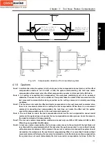
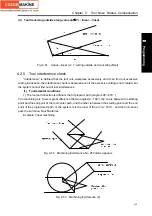
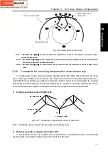
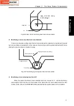
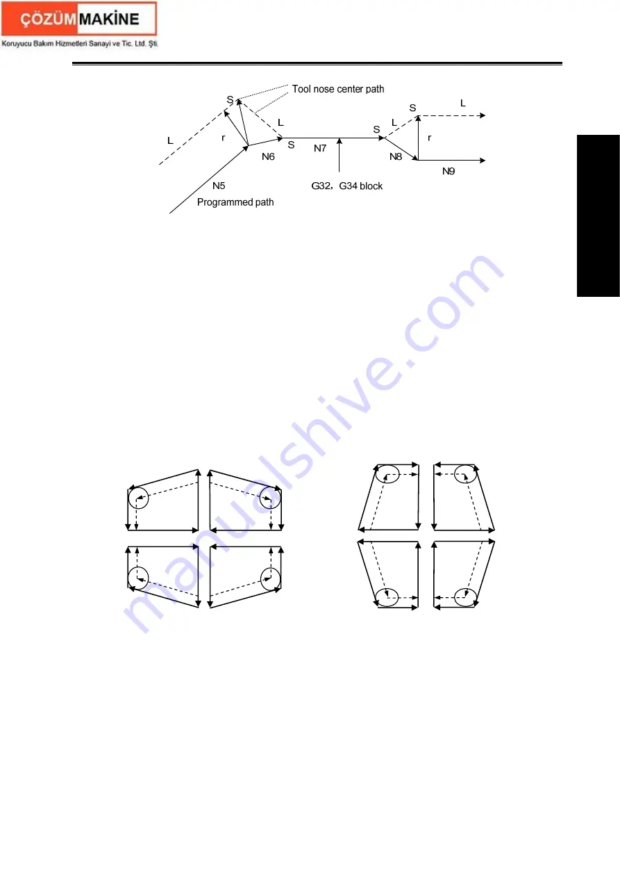
Fig.4-61 cancelling compensation vector in G32, G34 pause
z
G90, G94
Compensation method of tool nose radius compensation in G90 or G94:
A. Each cycle path and tool nose center path are parallel to program path.
B. Offset directions are the same in G41 and G42 as the following figure, and the system
determines the tool compensation direction according to the UW direction of starting point
and end point, and executes the tool compensation according to the direction in the cycle
process.
C. In having creating C tool compensation state, the system firstly cancels C tool compensation
state in G90, G94, and executes the infeed tool to the intersection point of the tool nose
center based on the tool nose center parallel programmed path, and at last to the positioning
point. The system creates C tool compensation again in the next G00, G01.
D. After the system cancels the tool radius compensation, the imaginary tool nose point moves
to the positioning point, and when the tool is in the cycle inner, the tool diameter exceeds the
length of the rapid traverse of the first block, the overcut creates and No.255 alarms.
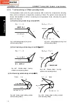
Fig. 4-62 Offset direction of tool
nose radius compensation in G90
Fig. 4-63 Offset direction of tool
nose radius compensation in G94
Summary of Contents for 988T
Page 6: ...GSK988T Turning CNC System User Manual VI ...
Page 14: ...GSK988T Turning CNC System User Manual XIV ...
Page 15: ...Chapter 1 Programming Fundamentals 1 Ⅰ Programming Ⅰ PROGRAMMING ...
Page 16: ...GSK988T Turning CNC System User Manual 2 Ⅰ Programming ...
Page 194: ...GSK988T Turning CNC System User Manual 180 Ⅰ Programming ...
Page 195: ...Chapter Ⅰ Overview 181 Ⅱ Operation Ⅱ OPERATION ...
Page 196: ...GSK988T Turning CNC System User Manual 182 Ⅱ Operation ...
Page 217: ...Chapter Ⅲ Windows 203 Ⅱ Operation ...
Page 267: ...Chapter Ⅲ Windows 253 Ⅱ Operation Fig 3 51 Fig 3 52 ...

