GSK988T Turning CNC System User Manual
166
Ⅰ
Programming
2
)
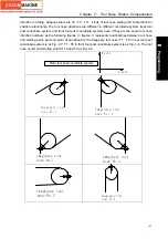
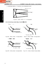
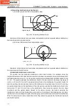
Center point and starting point of circular being the same one
Fig. 4-37 Center point and starting point of circular being the same one
z
Offset path of compensation direction in compensation mode
The compensation direction of tool nose radius is specified by G41 and G42 and the sign symbol
is as follows:
Table 4-4
Sign symbol of compensation value
G Command
+ -
G41 Left
compensation
Right compensation
G42
Right compensation
Left compensation
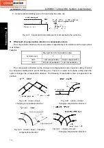
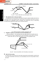
The compensation direction can be changed in compensation mode in special cutting, it cannot
be changed at starting block and its following one. There is no inside and outside cutting when the
system changes the compensation direction. The following compensation value is supposed to be
positive.
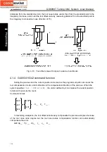
Fig. 4-38 Linear—linear
(
changing compensation direction
)
Fig. 4-39 Linear—circular
(
changing compensation direction
)
G42
S
C
r
G41
r
L
Programmed path
Tool nose center path
Fig. 4-40 circular—linear
(
changing
compensation direction
)
Fig. 4-41 circular—circular
(
changing compensation direction
)
Summary of Contents for 988T
Page 6: ...GSK988T Turning CNC System User Manual VI ...
Page 14: ...GSK988T Turning CNC System User Manual XIV ...
Page 15: ...Chapter 1 Programming Fundamentals 1 Ⅰ Programming Ⅰ PROGRAMMING ...
Page 16: ...GSK988T Turning CNC System User Manual 2 Ⅰ Programming ...
Page 194: ...GSK988T Turning CNC System User Manual 180 Ⅰ Programming ...
Page 195: ...Chapter Ⅰ Overview 181 Ⅱ Operation Ⅱ OPERATION ...
Page 196: ...GSK988T Turning CNC System User Manual 182 Ⅱ Operation ...
Page 217: ...Chapter Ⅲ Windows 203 Ⅱ Operation ...
Page 267: ...Chapter Ⅲ Windows 253 Ⅱ Operation Fig 3 51 Fig 3 52 ...


