GSK988T Turning CNC System User Manual
230
Ⅱ
Operation
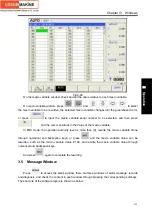
Fig.3-31
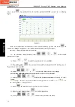
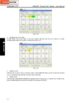
In the window, the user can search and set the too offset value and the wear value for each axis
corresponding to each tool offset number, and the concrete setting methods are referred to Chapter
6.6.
In the right side column of the tool offset setting, the system simultaneously displays the current
absolute coordinate values, the relative coordinate values and the tool number of the current program
running.
Note 1: The displayed axes in the window are set by the parameter No.1010 and No.8130, the rotary axis is not
displayed, the tool offset value is valid to the linear axis instead of the rotary axis.
Note 2: The linear axis and the rotary axis are specified (cannot be 0) by the axis attribution for each axis of
No.1022.
Note 3: The name for each axis is set by No.1020.
Note 4: No. 5004 Bit1 sets the tool offset value for each axis to be the diameter or the radius value designation;
No.1006 Bit3 sets the amount of movement for each axis to be the diameter or the radius designation.
Note 5: When the operation authority level is more than [4], the tool offset setting, the wear value setting and
others can be executed.
Note 6: The system supports the tool offset of the most 4 linear axes; when the linear axes is more than 4, the
system only displays 4 linear axes.
3.4.1.2 Tool life
Press[TOOL LIFE] to enter the tool offset setting window, which is shown in Fig.3-34:
Summary of Contents for 988T
Page 6: ...GSK988T Turning CNC System User Manual VI ...
Page 14: ...GSK988T Turning CNC System User Manual XIV ...
Page 15: ...Chapter 1 Programming Fundamentals 1 Ⅰ Programming Ⅰ PROGRAMMING ...
Page 16: ...GSK988T Turning CNC System User Manual 2 Ⅰ Programming ...
Page 194: ...GSK988T Turning CNC System User Manual 180 Ⅰ Programming ...
Page 195: ...Chapter Ⅰ Overview 181 Ⅱ Operation Ⅱ OPERATION ...
Page 196: ...GSK988T Turning CNC System User Manual 182 Ⅱ Operation ...
Page 217: ...Chapter Ⅲ Windows 203 Ⅱ Operation ...
Page 267: ...Chapter Ⅲ Windows 253 Ⅱ Operation Fig 3 51 Fig 3 52 ...

