GSK988T Turning CNC system User Manual
384
Appendix
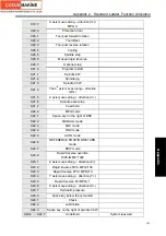
DB Pin PLC address
Function defined by standard PLC address
Remark
CN62.41
Y3.4
SORI
Spindle orientation signal
CN62.42
Y3.5
SEC0
Spindle orientation selection signal 1
CN62.43
Y3.6
SEC1
Spindle orientation selection signal 2
CN62.44
Y3.7
SEC2
Spindle orientation selection signal 3
CN62.17
~
CN62.19
CN62.26
~
CN6228
0V
CN62.20
~
CN62.25
+24V
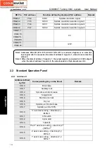
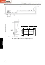
2.2 Standard Operation Panel
2.2.1 Address X
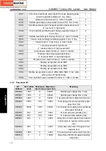
Address defined
by PLC
Corresponding Key on the Panel
Remark
X18.0 Block
skip
X18.1 Auxiliary
lock
X18.2
Spindle override increase
X18.3 Single
block
X18.4
Machine tool lock
X18.5 Dry
run
X18.6
Spindle override decrease
X18.7
Spindle override 100%
X19.0
C axis moves along – direction(C -)
/MPG C
X19.1 C/S
switch
X19.2 Cycle
start
X19.3 Tailstock
X19.4
The 4
th
axis moves along – direction (4
th
-)/MPG 4
th
X19.5
Z axis moves along – direction (Z-)/
MPG Z
X19.6
Y axis moves along – direction (Y-)/
MPG Y
Note1: Addresses X0.0~X0.7,X1.0~X1.7,X2.0~X2.7,X3.0~X3.7 are valid at a high-level, i.e. when the
input 24V is connected, the state of address X signal is 1; when disconnected, the
state is 0.
Note 2: When the state of address Y signal is 1, the output signal is connected to 0V (0V output);
when the sate of address Y signal is 0, the output signal is at high-impedance state.
Summary of Contents for 988T
Page 6: ...GSK988T Turning CNC System User Manual VI ...
Page 14: ...GSK988T Turning CNC System User Manual XIV ...
Page 15: ...Chapter 1 Programming Fundamentals 1 Ⅰ Programming Ⅰ PROGRAMMING ...
Page 16: ...GSK988T Turning CNC System User Manual 2 Ⅰ Programming ...
Page 194: ...GSK988T Turning CNC System User Manual 180 Ⅰ Programming ...
Page 195: ...Chapter Ⅰ Overview 181 Ⅱ Operation Ⅱ OPERATION ...
Page 196: ...GSK988T Turning CNC System User Manual 182 Ⅱ Operation ...
Page 217: ...Chapter Ⅲ Windows 203 Ⅱ Operation ...
Page 267: ...Chapter Ⅲ Windows 253 Ⅱ Operation Fig 3 51 Fig 3 52 ...


