GSK988T Turning CNC System User Manual
122
Ⅰ
Programming
④
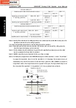
The tapping axis moves the hole bottom level at the cutting feedrate specified by F along
with the spindle rotation;
(
when the tool is about to reach the hole bottom position specified by the programmed, the
spindle stops M05 output and the spindle starts to decelerate, the tapping axis holds feed
until the spindle exactly stops rotation
)
⑤
Pause is executed in the time specified by P;
⑥
The spindle’s rotation M command (CW) outputs (the spindle rotation direction is reverse to
the tool infeed);
⑦
The tapping axis returns to point R level at the speed specified by F;
⑧
The spindle stops M05 output and rotation;
⑨
Return rapidly to the initial level;
⑩
Common tapping cycle ends.
Note 1
:
The command is for the flexible tapping and the tapping axis rotates along with the spindle
rotation. After the spindle stop signal M05 at the hole bottom is valid, the spindle stops rotation
in some deceleration time, at the moment, Z feeds along with the spindle rotation until the
spindle exactly stops. The hole bottom position is deeper or lower than the actual programmed
position, and the concrete error length is determined by the spindle speed and spindle brake
device in the course of tapping.
So, before tapping in G84/G88, the operator moves the slider to the safety position, and the
system executes G84/G88 without cutting the workpiece (it is not dry run). The operator actually
observes the coordinate difference between the position where the spindle stops at the hole
bottom and G84/G88 starting point, and then modifies the program to reserve the enough hole
depth before G84/G88 is executed.
Note 2
:
Before the tapping cycle is executed, the spindle’s rotation direction (i.e., command the spindle
rotation(CW or CCW) before the common tapping) can be specified according to the screw tap’s
rotation direction, the system starts to tap after the tool reaches point R, at the moment, the CNC
does not output spindle rotation M command, automatically counts the spindle rotation M
command in CCW direction after the tool reach the hole bottom. G84/G88 is executed in the next
block, and the tool has reached point R, the CNC again outputs the spindle rotation M command, at
the moment, the spindle’s rotation direction is consistent with that of the previous specified.
The CNC defaults to be spindle rotation (CW M03) when the spindle rotation is not specified. After
the fixed cycle is cancelled, the spindle stops rotation. Restart the spindle when the machining is
needed continuously.
Note 3: The traverse speed of tapping axis is determined by the spindle speed and pitch instead of the
cutting feedrate override; the spindle override is affected by N0.3708#6.
Note 4
:
When the single block runs or the system executes the feed hold, the system displays “Pause” but
the tapping cycle does not stop until the tapping is completed and the tool returns to the starting
Summary of Contents for 988T
Page 6: ...GSK988T Turning CNC System User Manual VI ...
Page 14: ...GSK988T Turning CNC System User Manual XIV ...
Page 15: ...Chapter 1 Programming Fundamentals 1 Ⅰ Programming Ⅰ PROGRAMMING ...
Page 16: ...GSK988T Turning CNC System User Manual 2 Ⅰ Programming ...
Page 194: ...GSK988T Turning CNC System User Manual 180 Ⅰ Programming ...
Page 195: ...Chapter Ⅰ Overview 181 Ⅱ Operation Ⅱ OPERATION ...
Page 196: ...GSK988T Turning CNC System User Manual 182 Ⅱ Operation ...
Page 217: ...Chapter Ⅲ Windows 203 Ⅱ Operation ...
Page 267: ...Chapter Ⅲ Windows 253 Ⅱ Operation Fig 3 51 Fig 3 52 ...


