GSK988T Turning CNC System User Manual
78
Ⅰ
Programming
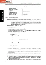
blocks are valid when executing ns
~
nf to command G70 finishing cycle.
3. There are only G00, G01 in ns block.
4. In ns
~
nf blocks, there are only G commands:G00, G01, G02, G03, G04, G96, G97,
G98, G99, G40, G41,G42 and the system cannot call subprograms(M98/M99)
5. G96, G97, G98, G99, G40, G41, G42 are invalid in G73 and valid in G70.
6. When G73 is executed, the system can stop the automatic run and manual traverse,
but return to the position before manual traversing when G73 is executed again,
otherwise, the following path will be wrong.
7. When the system is executing the feed hold or single block, the program pauses after
the system has executed end point of current path.
8. i
△
,
u are specified by the same U and
Δ
k
△
,
Δ
w are specified by the same U, and they
are different with or without being specified P, Q commands.
9. G73 cannot be executed in MDI, otherwise, the system alarms.
10. Z must be the monotonous in the cycle body specified by P and Q. Z tool retraction and
finishing allowance are set to 0 when the system executes X non-monotonous
workpiece. When No. 5102 Bit0 (MRI) is set to 1, the system does not alarm.
11. When the programming is executed, and the initial positioning point retreats one tool
infeed value in the direction of cutting but the result is in the contour range, the dry run
is executed to observe whether its own path of the system has overcutting because the
tool retraction direction is the same that of tool infeed in programming state.
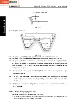
Relevant definitions:
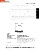
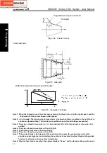
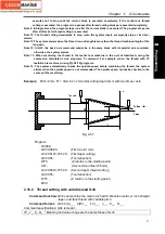
Finishing path The above-mentioned Part 3 of G73
(
ns
~
nf block)defines the finishing path, and
the starting point of finishing path (start point of ns block)is the same these of
starting point and end point of G73, called A point; the end point of the first block of
finishing path(ns block)is called B point; the end point of finishing path(end point of
nf block)is called C point. The finishing path is A
→
B
→
C.
Roughing path It is one group of offset path of finishing one, and the roughing path times are the
same that of cutting. After the coordinates offset, A, B, C of finishing path
separately corresponds to A
n,
B
n,
C
n
of roughing path(n is the cutting times, the first
cutting path is A
1
, B
1
, C
1
and the last one is A
d,
B
d,
C
d
). The coordinates offset value
of the first cutting compared to finishing path is
(
Δ
i×2+
Δ
u
,
Δ
w+
Δ
k
)(
diameter
programming
)
, the coordinates offset value of the last cutting compared to
finishing path is
(
Δ
u
,
Δ
w
),
the coordinates offset value of each cutting compared
to the previous one is
(
Δ
i×2/d-1
,
Δ
k/d-1
)
.
Δ
i
Travel of X tool retraction in roughing is the following table
(
radius value with sign
symbols
)
,
Δ
i is equal to X coordinate offset value
(
radius value
)
of A
1
point
compared to A
d
point. The X total cutting travel(radius value) is equal to |
Δ
i| in
roughing, and X cutting direction is opposite to the sign symbol of
Δ
i:
Δ
i
>
0, cut in
X negative direction in roughing. It is reserved after
Δ
i command value is executed
and the system rewrites No.5135 value. NO.5135 value is regarded as the travel
of X tool retraction of roughing when U
(
Δ
i
)
is not input.
Δ
k
Travel of Z tool retraction in roughing is the following table
(
radius value with sign
symbols
)
,
Δ
k is equal to X coordinate offset value
(
radius value
)
of A1point
compared to A
d
point. The Z total cutting travel(radius value) is equal to |
Δ
k| in
Summary of Contents for 988T
Page 6: ...GSK988T Turning CNC System User Manual VI ...
Page 14: ...GSK988T Turning CNC System User Manual XIV ...
Page 15: ...Chapter 1 Programming Fundamentals 1 Ⅰ Programming Ⅰ PROGRAMMING ...
Page 16: ...GSK988T Turning CNC System User Manual 2 Ⅰ Programming ...
Page 194: ...GSK988T Turning CNC System User Manual 180 Ⅰ Programming ...
Page 195: ...Chapter Ⅰ Overview 181 Ⅱ Operation Ⅱ OPERATION ...
Page 196: ...GSK988T Turning CNC System User Manual 182 Ⅱ Operation ...
Page 217: ...Chapter Ⅲ Windows 203 Ⅱ Operation ...
Page 267: ...Chapter Ⅲ Windows 253 Ⅱ Operation Fig 3 51 Fig 3 52 ...


