GSK988T Turning CNC System User Manual
X
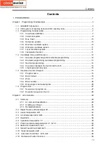
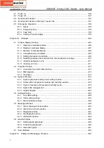
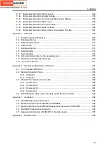
2.1 Power on ........................................................................................................................196
2.2 Power off.........................................................................................................................197
2.3 Overtravel Protection ......................................................................................................197
2.4 Overtravel Protection in Memory Travel Limit .................................................................197
2.5 Emergence Operation.....................................................................................................199
2.5.1 Reset ....................................................................................................................199
2.5.2 Emergency stop....................................................................................................199
2.5.3 Feed hold..............................................................................................................199
2.5.4 Cutting off power supply .......................................................................................199
Chapter
Ⅲ
Windows ...................................................................................................................200
3.1 Position Display Window ................................................................................................205
3.1.1 Absolute coordinate window .................................................................................206
3.1.2 Relative coordinate display...................................................................................207
3.1.3 Machine coordinate display ..................................................................................208
3.1.4 Comprehensive coordinate...................................................................................208
3.1.5 Setting the relative coordinate ..............................................................................209
3.1.6 Switching between the mode and the comprehensive message ..........................210
3.1.7 Clearing workpiece count ..................................................................................... 211
3.1.8 Clearing run time .................................................................................................. 211
3.2 Program Window ............................................................................................................212
3.2.1 Local directory and U disk directory......................................................................212
3.2.2 MDI program.........................................................................................................213
3.2.3 Item/times .............................................................................................................214
3.3 System Window ..............................................................................................................214
3.3.1 System parameter setting and rewriting window ..................................................215
3.3.2 Screw pitch compensation setting and rewriting window ......................................218
3.3.3 System message and operation authority levels ..................................................219
3.3.4 System file management ......................................................................................222
3.3.5 Ladder diagram ....................................................................................................223
3.4 Setting Window...............................................................................................................229
3.4.1 Tool offset setting..................................................................................................229
3.4.2 CNC setting window .............................................................................................233
3.4.3 Macro variable window .........................................................................................238
3.5 Message Window ...........................................................................................................239
3.5.1 Alarm message check window .............................................................................240
3.5.2 Alarm record check window..................................................................................241
3.5.3 Diagnosis window.................................................................................................242
3.5.4 Oscillograph window.............................................................................................245
3.5.5 GSK-CAN window ................................................................................................248
3.6 Graph Window ................................................................................................................249
3.6.1 Setting graph parameter .......................................................................................249
3.6.2 Processing graph path..........................................................................................250
3.6.3 Simulation graph...................................................................................................251
3.7 Help Windows.................................................................................................................252
Chapter
Ⅳ
Editing and Managing a Program .............................................................................254
Summary of Contents for 988T
Page 6: ...GSK988T Turning CNC System User Manual VI ...
Page 14: ...GSK988T Turning CNC System User Manual XIV ...
Page 15: ...Chapter 1 Programming Fundamentals 1 Ⅰ Programming Ⅰ PROGRAMMING ...
Page 16: ...GSK988T Turning CNC System User Manual 2 Ⅰ Programming ...
Page 194: ...GSK988T Turning CNC System User Manual 180 Ⅰ Programming ...
Page 195: ...Chapter Ⅰ Overview 181 Ⅱ Operation Ⅱ OPERATION ...
Page 196: ...GSK988T Turning CNC System User Manual 182 Ⅱ Operation ...
Page 217: ...Chapter Ⅲ Windows 203 Ⅱ Operation ...
Page 267: ...Chapter Ⅲ Windows 253 Ⅱ Operation Fig 3 51 Fig 3 52 ...


