Chapter
Ⅱ
G Commands
57
Ⅰ
Programming
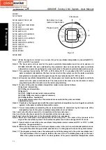
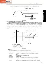
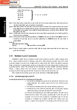
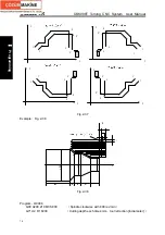
Fig. 2-24
Note 4: The coordinate offset value created by G50 adds to the one of all workpiece zero to make ensure
that all workpiece coordinate systems offset the same value as Fig. 3-21:
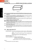
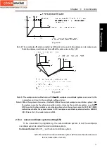
Fig. 2-25
Note 5: The workpiece zero offset value of G54
~
G59 workpiece coordinate system can be set in the
parameters and input in the coordinate setting window;
Note 6: When the system is turned on, it defaults G54 as the current workpiece coordinate system; after
the system executes the reference position return, it creates the coordinate system, uses G55
~
G59 to switch to other workpiece coordinate system; when the system resets, No.1201 Bit 7(WZR)
determines whether the system returns to G54 workpiece coordinate system; when No. 3402 Bit
6(CLR) is set to 1, the modal returns to G54.
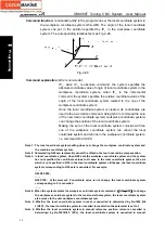
2.13.4 Local coordinate system setting G52
To be convenient to programming, the sub-coordinate system to set the workpiece
coordinate system is called the local coordinate system.
Command format:
G52 IP__; set the local coordinate system
……
G52 IP0; cancel the local coordinate system (IP0 means the absolute value
for each axis adds one zero)
Summary of Contents for 988T
Page 6: ...GSK988T Turning CNC System User Manual VI ...
Page 14: ...GSK988T Turning CNC System User Manual XIV ...
Page 15: ...Chapter 1 Programming Fundamentals 1 Ⅰ Programming Ⅰ PROGRAMMING ...
Page 16: ...GSK988T Turning CNC System User Manual 2 Ⅰ Programming ...
Page 194: ...GSK988T Turning CNC System User Manual 180 Ⅰ Programming ...
Page 195: ...Chapter Ⅰ Overview 181 Ⅱ Operation Ⅱ OPERATION ...
Page 196: ...GSK988T Turning CNC System User Manual 182 Ⅱ Operation ...
Page 217: ...Chapter Ⅲ Windows 203 Ⅱ Operation ...
Page 267: ...Chapter Ⅲ Windows 253 Ⅱ Operation Fig 3 51 Fig 3 52 ...

