Using negative logic for programmable I/O terminals
The negative logic signaling system can be used for the general-purpose input and output terminals
by setting the function code data specifying the properties for those terminals. Negative logic refers
to the inverted ON/OFF (logical value 1 (true)/0 (false)) state of input or output signal. An
active-ON signal (the function takes effect if the terminal is short-circuited.) in the normal logic
system is functionally equivalent to active-OFF signal (the function takes effect if the terminal is
opened.) in the negative logic system. An active-ON signal can be switched to active-OFF signal,
and vice versa, with the function code data setting.
To set the negative logic system for an I/O signal terminal, enter data of 1000s (by adding 1000 to
the data for the normal logic) in the corresponding function code.
For example, if the "Enable coast-to-stop" command
BX
(data = 7) is assigned to any one of digital
input terminals [X1] to [X8] by setting any of function codes E01 through E08, then turning
BX
on
will make the motor coast to a stop. Similarly, if the
BX
(data = 1007) is assigned, turning
BX
off
will make the motor coast to a stop.
Control mode
The FRENIC-Lift (LM2A) series of inverters supports the following control modes.
- Vector control with PG for asynchronous motor
- Vector control with PG for synchronous motor
- Torque vector control (without PG for asynchrnonous motor)
- V/f control (for asynchronous motor)
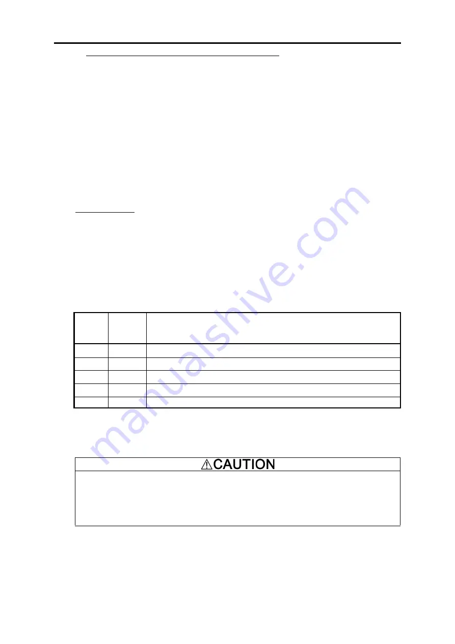
These control modes can be switched by the combination of function codes F42 (Control Mode) and
terminal command
PG/Hz
as listed below.
F42
(Control
Mode)
PG/Hz
*
1
Control Mode Selected
0
ON
Vector control with PG (for asynchronous motor) *
2
0
OFF
Torque Vector control (without PG for asynchronous motor)
1
ON
Vector control with PG (for synchronous motor) *
2
1
OFF
V/f control (for asynchronous motor)
2
ON/OFF Torque Vector control (without PG for asynchronous motor)
*
1
The ON/OFF states in this table are expressed in the normal logic. No assignment of
PG/Hz
to any
terminal is treated as ON.
*
2
An option card is needed. For details, refer to the instruction manual of the option card.
V/f control should apply to a test run only. Applying V/f control to elevator operation is
dangerous. With this setting, the inverter may not run in sufficient performance.
Torque Vector
control
is a control mode that doesn't use the encoder. The accuracy of the speed control is inferior
to that of the
vector control with PG.
Use it after doing the initial evaluation.
An accident or physical injury may result.
In the torque vector control, some function codes are invalid. Whether a function code is valid or
invalid is indicated with the following notations in the Torque vector control column of the function
code tables given below.
Y: Valid. (The function code data affects the inverter operations.)
N: Invalid. (The function code data does not affect the inverter operations.)
2-2
Summary of Contents for Frenic lift
Page 1: ...LM2A series Reference Manual INR SI47 1909a E...
Page 7: ......
Page 13: ......
Page 51: ...2 38...
Page 221: ......
Page 252: ......
Page 254: ...URL http www fujielectric com...


