background image


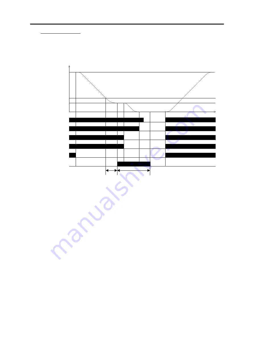
ii) When L99 bit6 is 1 

After the timer of L89, 

DOPEN

  is turned off regardless  to  the state of 

EN

  terminal  and 

BX


terminal. When the terminal 

BX

 is turned on, 

DOPEN

 output signal operates as same as 

EN

 is 

turned OFF. 
 

High speed

Speed

ON

FWD

SS1

SS2

ON

ON

SS4

ON

Creep speed

Zero speed

Time

ON

EN

DOPEN

ON

L88

L89

ON

ON

ON

ON

ON

ON

Door open

starting speed


2-180


Summary of Contents for Frenic lift

Page 1: ...LM2A series Reference Manual INR SI47 1909a E...

Page 2: ...ed herein is subject to change without prior notice for improvement The purpose of this manual is to provide accurate information in handling setting up and operating of the FRENIC Lift LM2A series of...

Page 3: ...correctly shorten their lives or cause problems The table below lists the other materials related to the use of the FRENIC Lift LM2A Read them in conjunction with this manual as necessary Name Materi...

Page 4: ...ch function code Chapter 3 OPERATION USING TP A1 LM2 This chapter describes how to operate FRENIC Lift LM2A using with optional multi function keypad TP A1 LM2A Icons The following icons are used thro...

Page 5: ...3 7 y codes Link functions 2 131 2 3 8 L codes Lift functions 2 140 2 3 9 K codes Keypad functions 2 202 Chapter 3 OPERATION USING TP A1 LM2 3 1 LCD monitor keys and LED indicators on the keypad 3 1 3...

Page 6: ...hapter describes the main block diagrams for the control logic of the FRENIC Lift LM2A Contents 1 1 Symbols Used inside the Block Diagrams and their meanings 1 1 1 2 Reference Speed pre ramp Command G...

Page 7: ......

Page 8: ...ning FWD Y1 etc Input output signals to from the inverter s control terminal block Function code FWD REV etc Control commands assigned to the control terminal block input signals Switch controlled by...

Page 9: ...5 L16 L17 L18 0 F01 Speed command 1 2 0 Enable communications link via RS485 or CAN LE Communications link operation xxx0 hex xxx1 hex 0 2 Loader link function E61 E62 E63 H30 y99 Multi function keypa...

Page 10: ...hing speed 1 L40 L41 Switching speed 2 ASR ASR feed forward gain L42 Js Reference torque F44 Current limiter L52 Starting torque generator Holding time Starting speed F24 F23 Starting speed H65 Soft s...

Page 11: ...P12 Motor Pulse encoder Output gate driver Alarm OC1 to OC3 Cooling fan control H06 Cooling fan control Power source Rectifier DC link bus capacitor Motor Cooling fan Reference torque bias Activation...

Page 12: ...2 2 Before setting the function code 2 22 2 3 Overview of Function Codes 2 23 2 3 1 F codes Fundamental functions 2 24 2 3 2 E codes Extension terminal functions 2 50 2 3 3 C codes Control functions...

Page 13: ......

Page 14: ...ata of the codes marked with Y is changed with keys the change will immediately take effect however the change is not saved into the inverter s memory To save the change press the key If you press the...

Page 15: ...motor Torque vector control without PG for asynchrnonous motor V f control for asynchronous motor These control modes can be switched by the combination of function codes F42 Control Mode and termina...

Page 16: ...ft blank means that the function is available since the first version The software version can be checked by the followings Maintenance screen PRG 3 3 8 9 or Unit information screen PRG 3 4 on the mul...

Page 17: ...1 Y2 Refer to default table 24 Y F12 Thermal time constant 0 5 to 75 0 0 1 min Y Y 2 0 3 Y F20 DC Braking Starting Speed 0 00 to 150 0 1 Equivalent with 0 00 to 5 00 Hz Variable 3 N Y 0 0 37 Y 8 F21 B...

Page 18: ...pole position offset tuning N 80 1080 CLC Customizable logic cancel Y 81 1081 CLTC Customizable logic all timer clear Y 98 FWD Run forward Y 99 REV Run reverse Y 100 NONE No function assigned Y 101 1...

Page 19: ...eleration Y 74 1074 DDEC During deceleration Y 75 1075 DZR During zero speed N 76 1076 PG ABN PG abnormal N 78 1078 DOPEN Door control Y 99 1099 ALM Alarm output Y 101 1101 DECF EN terminal detection...

Page 20: ...orque bias balance adjustment Offset BTBB N 20 Torque bias gain adjustment BTBG N E45 Reserved 4 Y Y 0 1 Y E46 Reserved 4 Y Y 1 1 Y E47 Reserved 4 Y Y 5 1 Y E48 LED Monitor Y Y 0 1 Speed monitor item...

Page 21: ...High Speed 5 Variable 3 Y Y 0 00 37 Y C16 High Speed 6 Variable 3 Y Y 0 00 37 Y C17 High Speed 7 Variable 3 Y Y 0 00 37 Y C18 High Speed 8 Variable 3 Y Y 0 00 37 Y C19 High Speed 9 Variable 3 Y Y 0 0...

Page 22: ...s stopped no load current is calculated by the motor constant 4 Enable Auto tuning current loop ACR proportional gain P06 No load current 0 00 to 500 0 Variable A N Y1 Y2 Refer to 24 Y default table P...

Page 23: ...tor temperature H27 Level 0 00 to 5 00 0 01 V Y Y 1 60 5 Y H30 Communications Link Operation Each digit of hexadecimal number specifies the source of Y Y 0000H 1 Y following commands Additionally foll...

Page 24: ...overload 0 Clears cumulative value of thermal by inverter power off 1 Y Y 0 1 Y 500 protection data for motor 1 Retains cumulative value of thermal after inverter power off H94 Cumulative Run Time of...

Page 25: ...r Timer 80 82 83 Falling edge detector Timer 90 92 93 Rising falling edges detector Timer 100 to 105 Hold Timer 110 Increment counter 120 Decrement counter 130 Timer with reset input Timer function Le...

Page 26: ...terminal 4106 5106 X6 terminal input signal only terminal 4107 5107 X7 terminal input signal only terminal 4108 5108 X8 terminal input signal only terminal 4110 5110 FWD terminal state only terminal 4...

Page 27: ...Y U123 User parameter 3 Variable Y Y 0 00 12 Y U124 User parameter 4 Variable Y Y 0 00 12 Y U125 User parameter 5 Variable Y Y 0 00 12 Y U126 User parameter 6 Variable Y Y 0 00 12 Y U127 User paramet...

Page 28: ...s Y Y OFF 1 Y 1 to 60 y09 Response latency time 0 00 to 1 00 0 01 s Y Y 0 01 5 Y y10 Protocol selection 0 Modbus RTU protocol Y Y 1 1 Y 1 SX protocol FRENIC Loader protocol 2 Reserved for particular m...

Page 29: ...o 15 Same as y34 0 Y Y 0 1 Y y35 Communication time out detection timer 0 0 to 60 0 0 1 s Y Y 0 0 3 Y y36 Operation selection in abort status 5 to 3 1 Y Y 1 2 y37 Compatibility selection 0 Standard 1...

Page 30: ...e if F42 1 1 to 4 It is a recommended condition that the brake is a close L09 Filter Time Constant for Reference Speed Final 0 000 to 0 100 0 001 s Y Y 0 000 7 Y L10 Filter Time Constant for Detected...

Page 31: ...00 0 01 s Y Y 1 00 5 N L60 Driving gain 1000 0 to 1000 0 0 1 Y Y 100 0 4 N L61 Braking gain 1000 0 to 1000 0 0 1 Y Y 100 0 4 N L62 Digital 1 200 to 200 1 Y Y 0 2 N L63 Digital 2 200 to 200 1 Y Y 0 2 N...

Page 32: ...2 3 N L105 Pluse 1 to 5 1 N Y 3 1 N L106 Speed limit 0 to 20 1 N Y 10 1 N L108 Encoder Rotation Detection speed 0 0 to 500 0 0 1 mm s N Y 10 0 3 N L109 Travel direction counter 6 Password setting 000...

Page 33: ...ly warning Y Bit1 Reserved Bit2 Reserved Bit3 Reserved Bit4 Reserved Bit5 Reserved Bit6 Reserved Bit7 Reserved L198 Operation setting switch 1 00000000b to 11111111b 0 to 255 N Y 00000000 0 1 Bit0 Fix...

Page 34: ...set BTBB N 30 Torque bias gain adjustment BTBG N K20 Bar chart 1 Y Y 1 1 K21 Bar chart 2 Y Y 13 1 K22 Bar chart 3 Y Y 19 1 1 Reference speed Final Y 13 Output current Y 14 Output voltage Y 18 Calculat...

Page 35: ...ue Hz F04 Base Speed 1 00 to 200 0 C03 Battery Operation Speed 0 00 to 200 0 F20 DCB Starting Speed 0 00 to 5 00 C04 Zero Speed to C19 High Speed 9 0 00 to 200 0 F23 Starting Speed 0 00 to 5 00 C20 Jo...

Page 36: ...n each code group its function codes are arranged in an ascending order of the identifying numbers for ease of access Note that function codes closely related each other for the implementation of an i...

Page 37: ...ous keying of or switches the password protection from disable to enable or vice versa respectively Data setting range 0000H Disable password protection 0001H to FFFFH Enable password protection Funct...

Page 38: ...e input terminal commands SS1 SS2 and SS4 with eight reference speeds pre ramp defined by C04 to C11 In the case of using SS8 reference speeds pre ramp are defined by C12 to C19 fixed combinations The...

Page 39: ...ON L14 00000011 b Creep speed defined by C07 OFF ON OFF OFF L15 00000100 b Manual speed low defined by C08 OFF ON OFF ON L16 00000101 b Low speed defined by C09 OFF ON ON OFF L17 00000110 b Middle spe...

Page 40: ...F L17 00000110 b Middle speed defined by C10 OFF ON ON ON L18 00000111 b High speed 1 defined by C11 ON OFF OFF ON High speed 2 defined by C12 ON OFF OFF OFF High speed 3 defined by C13 ON OFF ON OFF...

Page 41: ...07 F08 E13 F07 F08 E13 F07 F08 F07 F08 When the speed is changed to high speed 1 to 9 from the other of high speed E12 is used S curve starting ending zones to be applied when the reference speed pre...

Page 42: ...r a short floor operation On the contrary when the speed changes to acceleration during deceleration the inverter immediately starts S curve acceleration which may make an impact on the load Accelerat...

Page 43: ...4 Acceleration deceleration time 7 Time Creep speed Speed Zero speed L26 S curve setting 8 L28 S curve setting 10 L28 S curve setting 10 ON FWD SS1 SS2 ON ON SS4 ON Zero speed command Low speed comman...

Page 44: ...on deceleration time 5 E13 Acceleration deceleration time 6 L25 S curve setting 7 L24 S curve setting 6 ON EN1 EN2 Manual speed Low Time Speed ON FWD SS1 SS2 ON SS4 ON ON Zero speed command Manual spe...

Page 45: ...ation deceleration time 3 L22 S curve setting 4 L23 S curve setting 5 ON EN1 EN2 High speed Speed Time Zero speed Creep speed ON FWD SS1 SS2 ON ON SS4 ON Stop speed Output shut down H67 Stop speed Hol...

Page 46: ...is linear deceleration for the time specified by E16 when a run command is turned off during running Refer to the description of function code F23 for the timing chart to be applied when an analog sp...

Page 47: ...ause damage or a dangerous situation Make sure that the maximum speed setting matches the equipment rating Data setting range P01 1 120 to P01 200 120 r min Data setting range changes depending on the...

Page 48: ...eleration Deceleration Time 3 to 10 F07 and F08 specify the acceleration and deceleration times in linear acceleration deceleration zones excluding S curve zones The acceleration deceleration time is...

Page 49: ...rmal characteristics of the motor for its electronic thermal overload protection that is used to detect overload conditions of the motor by the inverter Select motor characteristics F10 F10 specifies...

Page 50: ...f the inverter In general set F11 to the allowable continuous drive current of the motor when driven at the rated speed i e 1 0 to 1 1 multiple of the rated current of the motor To disable the electro...

Page 51: ...2 38...

Page 52: ...F21 Sets the output current of the DC braking This level is used at start during H64 and at stop during F22 Data setting range 0 to 100 DC Braking Operation Time F22 The operation time of the DC brak...

Page 53: ...ro speed control time starts to count During this time motor is controlled at zero speed Brake will open as well BRKS to ON When this time is elapsed motor accelerates to starting speed according to s...

Page 54: ...ing speed turn the run command OFF once In case of Vector control with PG Speed start mode Setting L52 data to 0 enables the speed start mode i When a multistep speed command with S curve acceleration...

Page 55: ...H65 F24 Analog speed command Reference Speed Inverter does not start acceleration to the reference speed pre ramp as long as the reference speed pre ramp does not exceed the stop speed iii When an an...

Page 56: ...eed setting FWD SS1 Reference Toruqe Starting Speed 0 Reference Tourqe ON ON Detection Speed Starting Speed 0 Reference Speed Output Gate ON L85 H64 F24 s H65 100 t In case of Torque Vector control i...

Page 57: ...peed the inverter immediately accelerates from the current speed up to the reference speed pre ramp Speed 0 Starting Speed FWD ON SW52 2 ON Output Gate ON L85 H64 H65 Analog speed command Reference Sp...

Page 58: ...n 2 2 Detection method H66 H66 selects whether to use the detected speed or reference speed final for detecting the stop speed Data for H66 Function 0 Use detected speed 1 Use reference speed final In...

Page 59: ...he output current waveform to have a large amount of ripples many harmonics components As a result the motor loss increases causing the motor temperature to rise Furthermore the large amount of ripple...

Page 60: ...100 19 Inverter internal temperature Internal detection temperature of inverter 200 C 100 111 Customizable logic output signal 1 Only when analog output has been defined 100 100 112 Customizable logic...

Page 61: ...pectively These values are determined by the inverter and braking resistor models Default setting of these parameters might not be suitable for your braking resistor therefore before using this functi...

Page 62: ...raking time s Motor rated capacity kW 1 Allowable average loss F51 Allowable average loss is the required resistor capacity that allows continuous operation of motor It can be calculated from ED and m...

Page 63: ...art running or an abrupt change in speed An accident or physical injury may result Function code data Terminal commands assigned Symbol Active ON Active OFF 0 1000 Select multistep speed 1 SS1 1 1001...

Page 64: ...ecomes Active ON alarm is triggered when ON Terminal function assignment and data setting Select multistep speed SS1 SS2 SS4 and SS8 Function code data 0 1 2 and 3 The combination of the ON OFF states...

Page 65: ...al signals sent from the peripheral equipment via an RS485 or CAN communications link by feeding those signals to the digital input terminals Signals assigned to the universal DI are simply monitored...

Page 66: ...When this terminal command is OFF unbalance load compensation will be started after run command is ON For details refer to the descriptions of function codes L65 to L76 Unbalanced Load Compensation Ma...

Page 67: ...asing RTDEC Function code data 102 The inverter decreases reference torque to initial torque bias when turning RTDEC command OFF For details refer to the descriptions of function codes L99 bit2 Output...

Page 68: ...r will trip Er6 For details refer to the descriptions of function codes L120 and L121 Stand by mode STBY Function code data 117 When following conditions are met inverter enters Stand by mode STBY ter...

Page 69: ...nlocking safty gear operation ULSG Function code data 118 Turning this terminal command ON stars Unlocking safty gear operation For details refer to the descriptions of function codes L101 to L106 2 5...

Page 70: ...ignals chattering problems Mode E18 E18 specifies applicable commands for the agreement timer Data for E18 Applicable commands FWD REV SS1 SS2 SS4 SS8 0 1 2 3 Time E19 E19 specifies the period to conf...

Page 71: ...ll be opened and 30B and 30C closed This may be useful for the implementation of failsafe power systems When a negative logic is employed all output signals are active e g an alarm would be recognized...

Page 72: ...ting in reverse direction RRUN 55 1055 Run command activated AX2 56 1056 Motor overheat detected PTC THM 57 1057 Brake control BRKS 70 1070 Speed existence DNZS 71 1071 Speed agreement DSAG 72 1072 Sp...

Page 73: ...on LC1 128 1128 Loadcell Full load detection LCF 129 1129 Loadcell Overload detection LCO 141 1141 Customizable logic output signal 1 CLO1 142 1142 Customizable logic output signal 2 CLO2 143 1143 Cus...

Page 74: ...e detected speed drops below the Detection level E31 or E36 Hysteresis band width E32 These output signals are not affected by the run command For details refer to the description of function codes E3...

Page 75: ...ription of L93 Overheat Early Warning Level Service life alarm LIFE Function code data 30 This output signal comes ON when it is judged that the service life of any capacitors reservoir capacitor in t...

Page 76: ...g all of the following conditions Run command ON LU is OFF No alarm ALM is OFF This output signal comes OFF by satisfying either of the following conditions Run command OFF LU is ON Alarm ALM is ON Mo...

Page 77: ...tion code data 73 and 74 The output signal DACC or DDEC come ON depending on whether the motor is accelerating or decelerating by comparing the reference speed pre ramp with the detected speed These o...

Page 78: ...In other words it recommends always the braking direction If RRD is ON it means that inverter recomends rescue in FWD direction On the other hand if RRD is OF it means that inverter recomends rescue...

Page 79: ...ole tuning is not done the signal is OFF therefore the drive is informing to the external equipment that Pole tuning must be performed If pole tuning is performed PTD signal is set to ON when the tuni...

Page 80: ...ls refer to the descriptions of function codes L109 to L115 TDC and L197 For additional information refer to related Application Note AN Lift2 0004v100EN Travel Direction Changes pulse TDCP Function c...

Page 81: ...cted is equal or higher than L146 level and below L147 After RUN command is removed it turns automatically to OFF When torque detected is out of torque range specified by levels L146 and L147 and time...

Page 82: ...FAR3 comes ON when the detected speed against the reference speed pre ramp is within the specified range This output signal is not affected by any run command The output signals DACC and DDEC can be a...

Page 83: ...steresis E32 The FDT is turned OFF when the detected speed becomes lower than the Detection level E31 or E36 Hysteresis band width E32 Data setting range 0 00 to 900 r min Data setting range changes d...

Page 84: ...the inverter has exceeded the level specified by E34 for ID or by E37 for ID2 and the output current continues longer than the period specified by E35 Current detection time It turns OFF when the outp...

Page 85: ...que Reference torque based on the motor rated torque 19 Torque bias balance adjustment Offset BTBB For adjustment of analog torque bias 20 Torque bias gain adjustment BTBG 1 In vector control with PG...

Page 86: ...ck setup Quick setup function code 1 f__ Data setting F to o F to K group function code 2 rep Data check Modified function code 3 ope Operation monitor Operation status indication 4 i_o I O check DIO...

Page 87: ...V2 V2 function by 0 to 10 VDC and V2 C1 function by 4 to 20 mADC for 0 to 100 of the maximum speed 2 Speed command Operation is reversible with the polarity Input an analog speed command to terminal 1...

Page 88: ...8 Command Assignment to X1 to X8 E99 Command Assignment to REV E01 to E08 Command Assignment to X1 to X8 Function codes E98 and E99 specify the functions assigned to terminals FWD and REV For details...

Page 89: ...Manual Speed Middle Output frequency C03 The inverter stops ON ON ON ON ON E17 0 Input power C01 0 C02 IPL ON The inverter stops automatically BRKS ON C03 Battery Operation Speed C03 specifies the ba...

Page 90: ...power supply goes OFF battery power supply and control power supply turns ON 200ms The control power supply remains ON or after momentary power failure happens 200ms Table 1 Delay time from BATRY ON t...

Page 91: ...k Safety coefficient less than 1 and may be about 0 8 Connection diagram in case of batteries and FRN0032LM2A 4_ or below Connection diagram in case of batteries and FRN0039LM2A 4_ or above 73X MC2 R...

Page 92: ...and battery power supply are turned ON After that the inverter becomes ready to run 3 The BATRY should not be turned ON as long as the voltage level is higher than the specified undervoltage level tha...

Page 93: ...e changes depending on the number of poles of motor etc For details refer to section 2 2 Jogging operation The terminal command JOG can be assigned to a programmable input terminal by setting 10 With...

Page 94: ...ion codes For details refer to section 2 2 Relational equations between Hz and other units 1 r min and Hz Pe Hz r 120 min 2 m min and Hz 1000 60 120 max max min Pe Hz N V m 3 mm s and Hz Pe Hz N V s m...

Page 95: ...ommand value Analog input Offset Gain Reference value Where the analog input 100 to 100 corresponds to 10 to 10 V in voltage input and 0 to 100 to 4 to 20 mA in current input The table below lists the...

Page 96: ...nd 40 offset Adjust gain with 0 offset Adjust offset with 100 gain Adjust offset and gain 11V 11V 11V 11V 11V 11V 10V 20 mA 10V 20 mA 0V 4 mA 0V 4 mA Filter time constant C33 C38 and C43 These functio...

Page 97: ...ging the P01 data requires modifying the data of some function codes For details refer to section 2 2 P02 Motor Rated capacity P02 specifies the rated capacity of the motor Enter the rated value shown...

Page 98: ...tance X P08 2 Tune the motor while it is stopped Tune R1 X no load current and rated slip while the motor is stopped No load current P06 Primary resistance R1 P07 Leakage reactance X P08 Rated slip fr...

Page 99: ...wing formula 100 I 3 V R1 Cable R1 R1 where R1 Primary resistance of the motor Cable R1 Resistance of the output cable V Rated voltage of the motor V I Rated current of the motor A Data setting range...

Page 100: ...p frequency of the motor Data setting range 0 00 to 15 00 Hz The rated slip frequency is calculated with the following formula r min speed s Synchronou r min speed Rated r min speed s Synchronou Hz fr...

Page 101: ...alization all except communications function codes 12 Limited initialization initialization of customizable logic function U U1 codes Upon completion of the initialization the H03 data reverts to 0 fa...

Page 102: ...s 0 60 r min E36 Speed Detection 2 FDT2 Detection level 60 00 r min C03 Battery Operation speed 2 00 r min C06 Maintenance Speed 20 00 r min C07 Creep Speed 3 00 r min C11 High Speed 1 60 00 r min C20...

Page 103: ...ly releasing the tripped state If the protective function is activated more than the specified auto reset times the inverter issues an alarm for any faults and does not attempt to release the tripped...

Page 104: ...be reset only H04 times not infinite times Alarm codes crossreference with H82 bits 15 14 13 12 11 10 9 8 7 6 5 4 3 2 1 0 Eo OH6 Er6 1 ErE OL1 OH4 OH3 OH1 OLU LV OVn 2 OCn 2 1 Only for subcode 8 and 1...

Page 105: ...n code data 56 by which a temperature alarm condition can be indicated to the external equipment 3 Enable When the voltage sensed by the NTC thermistor exceeds the detection level the motor protective...

Page 106: ...ink or the CAN communications link and setting means of speed command and run command RS485 CAN Link function selection Terminal LE unassigned Terminal LE ON 0 1 y99 H30 Loader link function selection...

Page 107: ...verter itself take control H42 Capacitance of DC Link Bus Capacitor H42 displays the measured capacitance of the DC link bus capacitor reservoir capacitor Data setting range 0 to 65535 H43 Cumulative...

Page 108: ...peed to 0 00 r min Data setting range 0 00 to 99 9 s Forced to decelerate The DRS command can be assigned to a general purpose programmable input terminal by setting 66 The DRS should be ON when the i...

Page 109: ...Speed Soft start time F23 Starting Speed H65 specifies the acceleration time until the speed reaches the starting speed The specified time is the one required for accelerating from 0 00 to the startin...

Page 110: ...se programmable output terminal by setting 71 The DSAG comes ON regardless of the status of a run command when the difference between the commanded and detected speeds is within the hysteresis band sp...

Page 111: ...the inverter H81 Auto Reset Mode selection 1 H04 Auto reset Times H05 Auto reset Reset interval H82 Auto Reset Mode selection 2 Certain alarm codes can be automatically reset as explained on the funct...

Page 112: ...detected brake status is not correct the operation of the elevator must be prevented It is applicable as well to the lift standards EN 81 20 2014 and EN81 50 2014 This function is not active in factor...

Page 113: ...as BRKS function is OFF and L84 timer is elapsed On the following figures each possible scenario using BRKE1 and BRKE2 input functions is described a Brake feedback not matching with brake control sig...

Page 114: ...feedback not matching with brake control signal during travel ON Speed 0 High speed Creep speed FWD SS1 SS2 SS4 ON ON ON ON BRKE1 Brake1 Release BRKS ON Stop speed F25 H67 L82 L84 L83 L84 BRKE2 ALM Br...

Page 115: ...rated d Brake feedback is abnormal when motor is stopped In this case there are two possibilities with and without RBRK function active Rescue operation by external brake control active ON Speed 0 FWD...

Page 116: ...alarm for this function Also alarm Er6 has a SUB code related to this function Additional information for each alarm is described in table below Table 1 Alarms and SUB codes Alarm message displayed S...

Page 117: ...nance Function F26 Motor Sound Carrier frequency H98 specifies whether to enable or disable automatic lowering of the carrier frequency protection against input phase loss judgment on the DC link bus...

Page 118: ...link voltage Detect output phase loss OPL Bit 2 This function can detect the output phase loss This function becomes effective by H98 bit2 1 OPL is displayed when the loss is detected and the inverter...

Page 119: ...INR SI47 1894 E Chapter 6 MAINTENANCE AND INSPECTION Starting speed Starting speed Setting speed Reference speed L85 H65 F24 0 0 Gate Run command ON ON 500ms EN ON SW52 2 ON ON ON Output phase loss d...

Page 120: ...t data of bit 6 to 0 when the inverter does not use a braking transistor and there is no need of entering the alarm state Canceling detection of thermistor cut line Bit 7 400V series 37kW and above Fo...

Page 121: ...al output 1 analog output Number of steps 200 steps Customizable logic output signal 10 outputs Customizable logic processing time 2 ms max 10 steps 5 ms max 50 steps 10 ms max 100 steps 20ms max 200...

Page 122: ...1 SO002 SO200 CLO1 1 U71 Disable 0 1 2 200 SO001 SO002 SO200 CLO3 2 U73 3 SO003 4 SO004 Inverter Application Process FSET NP FSET P FOUT1 FOUT2 IOUT VOUT Internal input signal Internal output signal 1...

Page 123: ...customizable logic function or disable it to run the inverter only via its input terminals or others U00 data Function 0 Disable 1 Enable Customizable logic operation The ECL alarm occurs when changi...

Page 124: ...U17 U18 U19 U20 SO004 Step 5 U21 U22 U23 U24 U25 SO005 Step 6 U26 U27 U28 U29 U30 SO006 Step 7 U31 U32 U33 U34 U35 SO007 Step 8 U36 U37 U38 U39 U40 SO008 Step 9 U41 U42 U43 U44 U45 SO009 Step 10 U46...

Page 125: ...F pulses whose lengths are specified by the timer alternately and repeatedly This function is used to flash a luminescent device 20 to 25 Logical AND General purpose timer AND function with 2 inputs a...

Page 126: ...value 130 Timer with reset input Timer output with reset input If the input signal turns ON the output signal turns ON and the timer starts When the period specified by the timer has elapsed the outp...

Page 127: ...al purpose timer Rising falling edges detector Data 10 Hold Output Input 1 Input 2 General purpose timer 0 1 Data 110 Increment counter Output Input 1 Input 2 Increment counter Count cleared Data 120...

Page 128: ...elay timer OFF ON Timer Input Output Time setting value OFF ON OFF OFF ON ON ON OFF End 3 One shot pulse output OFF ON Timer Input Output Time setting value OFF OFF ON ON OFF OFF OFF End 4 Retriggerab...

Page 129: ...001 to to 2200 3200 Output of step 200 SO200 4001 5001 Terminal X1 input signal X1 4002 5002 Terminal X2 input signal X2 4003 5003 Terminal X3 input signal X3 4004 5004 Terminal X4 input signal X4 400...

Page 130: ...it value Upper limit Lower limit 2002 Subtracter Subtraction function with two inputs input 1 and input 2 This function has output limiters upper lower specified with two function codes The 1st functi...

Page 131: ...s width or smaller this function outputs logical 0 False Threshold value Hysteres is width 2052 Comparator 2 Comparison function with hysteresis This function compares the differential value between i...

Page 132: ...1 is outside of this range this function outputs logical 0 False Upper threshold Lower threshold 2072 Window comparator 2 Comparison function with limit This function has the inverted logic of Window...

Page 133: ...omparator 1 Output Input 1 Input 2 With Input 1 Input 2 U04 U05 Output ON With Input 1 Input 2 U04 U05 Output OFF 2052 Comparator 2 Output Input 1 Input 2 With Input 1 Input 2 U04 U05 Output ON With I...

Page 134: ...U04 2072 Window comparator 2 Output Input 1 Input 2 With U04 Input 1 U05 Output ON With Input 1 U04 U05 Input 1 Output OFF U05 U04 2101 High selector 2102 Low selector 2103 Average of inputs Input 1 I...

Page 135: ...as 100 00 Note 10 Universal AO is not available to 8019 2001 to 2200 Output of step 1 to 200 SO001 to SO200 9001 Analog 12 terminal input signal 12 9002 Analog C1 terminal input signal V2 C1 function...

Page 136: ...digital input 1 is 0 the analog input 1 is directly output LPF maintains the previous output value Therefore when the digital 1 input changes from 0 to 1 the output will be the value with the previou...

Page 137: ...12 22 24 29 35 37 45 61 67 68 74 92 and 93 Data formats other than the above cannot be read correctly Do not use them 0 to 255 0 to 99 6002 Writing function codes This function writes the value of in...

Page 138: ...restored when the inverter is powered on Set the function code group function type code to the1st function code U04 etc Set the lower 2 digits of the function code No to the 2nd function U05 etc If t...

Page 139: ...U04 Output Input 1 Input 2 0 0 LPF 4006 Rate limiter with enable U04 Output Input 1 Input 2 0 0 rate limiter 5000 Selector 3 Output Input 1 Input 2 0 0 SO15 U04 5100 Selector 4 S015 Output Input 1 In...

Page 140: ...o 10 CLO1 to CLO10 U71 to U80 Select an analog input function to which one of the customizable logic output signals 1 to 10 CLO1 to CLO10 is to be connected same as in E61 U81 to U90 General purpose d...

Page 141: ...on If the step output is digital The same value as E98 can be specified 0 1000 Select multistep speed 1 0 to 1 steps SS1 1 1001 Select multistep speed 1 0 to 3 steps SS2 2 1002 Select multistep speed...

Page 142: ...n deceleration time 9 E17 Acceleration deceleration time 10 L09 Filter Time Constant for Reference Speed Final L10 Filter Time Constant for Detected Speed L36 ASR P constant at high speed L37 ASR I ti...

Page 143: ...trol function K 28 Keypad function P 3 Motor1 M 8 Monitor H 4 High performance function W 15 Monitor 2 H1 31 High performance function W1 22 Monitor 3 U 11 Customizable logic W2 23 Monitor 4 U1 39 Cus...

Page 144: ...tart an operation or start an unexpected action Fully ensure it is safe before performing the operation An accident or physical injury may occur Customizable logic timer monitor Step selection U91 X89...

Page 145: ...eration depending on the settings Ensure the safety and check the operation before switching the signal Clear all customizable logic timers CLTC function codes E01 to E08 Data 81 If the CLTC terminal...

Page 146: ...lable 2 Inverter supporting loader FRENIC loader Inverter supporting monitor function code editing test operation can be performed by connecting a computer with the FRENIC Loader software installed Fo...

Page 147: ...od specified in the error process timer displays the RS 485 communication error Er8 for y02 ErP for y12 and stops the operation trip by alarm 3 Continues the operation if a communication error occurs...

Page 148: ...sponse interval time y09 y19 Sets a period from the time when the system receives a request from host equipment upper equipment such as computer or PLC until the time when it returns a response In cas...

Page 149: ...the inverter function code read to be mapped to TPDO No 3 Specify the function code type and number in a 4 digit hexadecimal notation Type Group code Type Group code S 0x02 2 X1 0x1A 26 M 0x03 3 X2 0x...

Page 150: ...of communication abort occurs y36 data Function 5 Error with NMT state check 4 Error without NMT state check 3 No error with NMT state check 2 No error with NMT state check 1 Immediate error with NMT...

Page 151: ...ta Function 0 Speed command S01 S21 1 Acceleration command S16 S17 y95 Communication data storage selection If any of the communication error alarms Er8 ErP Ert occurs in RS 485 or CANopen communicati...

Page 152: ...ory to nonvolatile memory After storing all data the y97 data returns to 1 y99 Loader Link Function Mode This is a link switching function for FRENIC Loader Setting the function code data y99 with the...

Page 153: ...PSH Synchronous motor 5 Sinusoidal differential voltage 1 Vp p SIN COS HEIDENHAIN ERN1387 or its equivalent OPC PR Synchronous motor 6 Sinusoidal differential voltage 1 Vp p BiSS C Kubler Sendix5873 o...

Page 154: ...r No of poles P01 Set the number of poles of the motor Motor Rated capacity P02 Set the rated capacity of the motor Motor Rated current P03 Set the rated current of the motor Motor R1 P07 Set 5 Motor...

Page 155: ...Regulator are set by parameters L05 and L06 respectively Data setting range L05 0 0 to 15 0 Data setting range L06 0 01 to 5 00 ms L07 Automatic pole tuning selection The automatic magnetic pole posit...

Page 156: ...control power supply The magnetic pole position tuning doesn t operate when providing second and following operation commands The validation test must be done for every type of motor to use with this...

Page 157: ...etails L29 Short Floor Operation Holding time L30 Short Floor Operation Allowable speed L29 and L30 specify a short floor operation that applies when a deceleration command is entered during accelerat...

Page 158: ...eed command Creep speed command Zero speed command L24 S curve setting 6 L28 S curve setting 10 L28 S curve setting 10 E14 Acceleration deceleration time 7 In case of Reference speed final Allowable s...

Page 159: ...peed command Creep speed command Zero speed command L19 L28 L28 L26 E13 E12 L25x0 2 L24 FWD SS1 SS2 SS4 L25x0 2 E14 In case of Reference speed final Allowable speed L30 and Holding time L29 OFF when a...

Page 160: ...er to section 2 2 L32 Elevator Parameter Over speed protection level L32 specifies over speed protection level If the speed of motor exceeds the over speed protection level for a duration longer than...

Page 161: ...L31 Elevator speed 1 to 4000 mm s This code specifies the elevator speed relative to the inverter s maximum speed L34 Moving distance in creepless operation 0 0 to 6553 5 mm This code specifies the m...

Page 162: ...one specified Sc Sd Tdec Speed r min Time t s Start Maximum speed Stop Sa Sb Tacc Deceleration N 0 The elevator cage moves by distance L calculated by equations 1 and 2 when the elevator decelerates f...

Page 163: ...operation command The graph below shows a basic pattern of a creepless operation using the Start creepless operation command CRPLS The CRPLS command should be given within zone A ranging from the end...

Page 164: ...lessen the number of terminals which should be switched Changing the setting of only a single terminal for changing the reference speed pre ramp can suppress the fluctuation of signals issued from th...

Page 165: ...1 For details about the ASR switching speed refer to the descriptions of L40 and L41 ASR P constant L36 and L38 The P constant should be specified in proportion to the inertia and machine constants of...

Page 166: ...speed 1 L41 Switching speed 2 Reference speed final L36 constant L37 I constant at high speed ASR constant and I constant L42 ASR Feed forward gain The FRENIC Lift LM2A series of inverters supports t...

Page 167: ...at can be a vibration element and applies it to the reference torque for canceling the load torque This way the observer quickly attenuates the vibration caused by resonance of machinery Gain L49 L49...

Page 168: ...on and the clockwise rotation the reverse direction A positive torque bias corresponds to forward direction torque 12 Driving gain Braking gain L60 L61 C1 V2 C42 Gain Reference torque to inverter C41...

Page 169: ...36 V2 C1 function or C41 V2 V2 function so that the monitored data comes to 0 The monitored data shows the ratio to the motor rating torque in percentages Gain adjustment 1 The gain adjustment should...

Page 170: ...se a torque bias hold command and startup timer described in the description of L55 Torque bias startup timer TB1 TB2 Torque bias value OFF OFF Specified by L62 Data setting range 200 to 200 with the...

Page 171: ...cified torque bias in the time length proportional to L55 Note that L55 specifies the time length required from the start of running until the torque changes from 0 to 100 of the motor rated torque On...

Page 172: ...equence in speed control the inverter decreases the reference torque value held internally to 0 taking time proportional to the value set in L56 Note that L56 sets the time length required to decrease...

Page 173: ...n PI torque bias Data setting range 0 00 to 1 00 s Refer to the description of function code L54 for details L60 Torque Bias Driving gain L54 Torque Bias Mode L61 Torque Bias Braking gain L54 Torque B...

Page 174: ...Name Setting required E01 to E08 E98 and E99 Command assignment to terminals X1 to X8 Setting 67 assigns UNBL Turn the UNBL ON to start estimating an unbalanced load and start L66 and L67 timers If no...

Page 175: ...command Zero speed command Release Brake Charge Torque bias 4 Torque command inside the inverter L57 SS1 SS2 High speed Creep speed UNBL ON ON SS4 L66 L55 1 3 2 Details 1 During the period from the e...

Page 176: ...t than the one specified in normal operation If vibration occurs increase it Data setting range 0 001 to 1 000 s L73 Unbalance load compensation APR P constant L73 specifies the APR Automatic Position...

Page 177: ...psed OR The inverter output is shut down Except conditions given at left 2 A run command is ON AND Output current Motor no load current x L81 AND The inverter main circuit output gate is kept ON durin...

Page 178: ...er turn ON again even the ON conditions are met again To turn the BRKS signal ON again turn the run command OFF once Brake confirmation signal BRKE Setting 65 to any of the general purpose programmabl...

Page 179: ...E Brake Release ON BRKS ON ON Stop speed Zero speed command Inverter trip ON H67 L82 Over L84 L82 Within L84 L83 Within L84 When L80 2 Speed 0 High speed Creep speed FWD SS1 SS2 SS4 ON ON ON ON Zero s...

Page 180: ...or turning the MC control signal SW52 2 ON or OFF The timing diagram is shown on the next page SW52 2 ON SW52 2 OFF Current status retained 1 When all of the following conditions are met turning a run...

Page 181: ...al 2 SW52 3 Timing diagram MC Operation confirmation CS MC is assigned to a general purpose programmable input terminal by setting 103 with E01 to E08 E98 and E99 This signal checks that the output si...

Page 182: ...ON ON ON Er6 trip Timer is reset Run command ON SW52 3 ON EN SW52 3 CS MS L84 timer ON ON ON Er6 trip Timer is reset Run command ON SW52 2 ON SW52 2 Timing Scheme SW52 3 Timing Scheme Function code of...

Page 183: ...control When the reference speed final drops below the door open starting speed L87 during deceleration and the door open delay time L88 elapses the DOPEN is turned ON and kept ON during the door ope...

Page 184: ...d final Detected speed If L90 0 When the speed is within domains through in the above graph the inverter regards it as an error Independent of the PG error detection the inverter continues to run If a...

Page 185: ...signal OH is assigned to a general purpose programmable output terminal by setting E20 to E24 and E27 to 28 Data setting range 1 to 20 deg ON conditions OFF conditions Current status retained When any...

Page 186: ...ing operation Bit 0 The inverter stops when reference torque current of the inverter exceeds the over torque current detection level E34 and the reference torque current continues longer than the peri...

Page 187: ...curence Both type of alarms occurrence Alarm occur ON ON Driving Drive Drive continuance stop Inverter driving Driving signal RUN Drive continuance alarm ALM2 Alarm output ALM Object alarm 10s Alarm o...

Page 188: ...N function change S1 bit selection for DCP Rise direction definition Short floor operation using s curve control driving Initial torque bias and reference torque decreasin g Magnetic pole position off...

Page 189: ...ction code L55 Output gate Torque bias analog input Reference torque bias ON L55 B A A Set point of torque bias B A 100 L57 A Initial torque bias Set point of torque bias b Reference torque decreasing...

Page 190: ...1 The deceleration instruction to the creep speed C07 is given while accelerating to Low speed C09 Middle speed C10 or High speed C11 from Zero speed C04 or STOP S curve used is 10 or more Figure to T...

Page 191: ...tting 7 E12 Acceleration deceler ation time 5 L24 S curve setting 6 FWD SS1 SS2 SS4 E14 Acceleration deceleration time 7 When the instruction to creep velocity is given while accelerating to high spee...

Page 192: ...SW52 2 or SW52 3 for DCP protocol communication L99 bit5 0 S1 bit is the same as the operation of SW52 2 L99 bit5 1 S1 bit is the same as the operation of SW52 3 DOPEN function change Bit 6 The functi...

Page 193: ...the state of EN terminal and BX terminal When the terminal BX is turned on DOPEN output signal operates as same as EN is turned OFF High speed Speed ON FWD SS1 SS2 ON ON SS4 ON Creep speed Zero speed...

Page 194: ...he value set on L102 Data setting range 0 1 to 2 0 s Unlock Safety Gear Reset time L104 L104 specifies the time between two consecutive pulses Data setting range 0 1 to 1 0 s Unlock Safety Gear Pulse...

Page 195: ...is not defined in L109 TDC function remains disabled Data for L109 Action 0000h No password Function disabled 0001h FFFFh Password setting range As soon as password is defined L109 returns to default...

Page 196: ...has been changed When this parameter is modified value is changed reset counter L115 is increased one unit By definition this parameter cannot be bigger than L111 limit When L113 L111 inverter will t...

Page 197: ...mber of resets L115 This is READ ONLY function code It shows the total number of reset operations This counter increments one unit each time that parameter L113 is modified For additional information...

Page 198: ...oken It is understood as no speed detected no movement any speed below speed level set on L108 When speed is below L108 timer L119 starts to count If speed doesn t reach speed level set on L108 when t...

Page 199: ...gure 3 Inverter locked by rbA case 1 Figure 4 shows a second case where inverter is locked by rbA alarm As soon as rescue operation by brake control starts motor speed increases because lift car moves...

Page 200: ...re short circuited to have an additional safety On the other hand market trend is moving to contactorless solutions Without contactors the installation wiring is easier there is less maintenance and a...

Page 201: ...lly closed contact with programmable delay at closing In this case in order to avoid extra delays L86 can be set to 0 00s If the programmable delay is not used L86 should be set to greater than defaul...

Page 202: ...rivers are OFF and brake is closed brake is closed no regenerated energy can flow from the motor In figure 2 an emergency stop timing sequence is shown Speed 0 High speed Run command FWD REV ON SCC Sh...

Page 203: ...ter trips SCA Alarm ON Feedback is lost Figure 5 Feedback problem during normal travel SCA alarm As it can be observed during motion no timer is considered in other words if feedback is lost SCCF inpu...

Page 204: ...s when short circuit is not done in other words it avoids that contacts closed while motor is already generating energy For a similar reason when rescue operation by brake control finishes RBRK is OFF...

Page 205: ...PEN CLOSED OFF ON OPEN ON OFF Figure 9 STBY function enabled L122 Deliverance Operation Input power detection level L123 Deliverance Operation Direction Calculation Setup L124 Deliverance Operation Di...

Page 206: ...urn the motor always in FWD direction If level 121 is not reached deliverance operation will be finished when RUN command is removed 1 Move in FWD and REV direction Regardless of input terminal activa...

Page 207: ...ts because DC link voltage level is over L125 In figure 2 a rescue operation sequence when DC link voltage is below L125 level is shown Main power MC1 BATRY MC2 73X UPS batteries power supply DC link...

Page 208: ...Theta compensation band is used for a better accuracy on Vector control with peripheral PG Synchronous motor Please don t modify this parameter default setting is the optimal value Theta compensation...

Page 209: ...nic name plate Mode L136 L101 specifies the operation of Encorder Electronic name plate Data setting range 0 Disable 1 Read 2 Write To change the L136 data it is necessary to press the keys simultaneo...

Page 210: ...eter will be understood as torque needed to keep zero speed when one person or a certain level of load is inside the car In order to set L145 correctly please check torque at zero speed when one perso...

Page 211: ...ed to keep zero speed when car is full In order to set L146 correctly please check torque at zero speed when full load is inside car after rollback is compensated Speed mm s Run command FWD REV ON BRK...

Page 212: ...d when maximum load allowed is inside car after rollback is compensated Speed mm s Run command FWD REV ON BRKS L144 Mechanical brake Opened ON EN1 EN2 ON Torque L147 LCO ON Figure 3 Overload detection...

Page 213: ...elapsed because torque is over L147 level output function LCO is going to ON state After 0 2 s in order to make sure brake is closed before current is removed LCO alarm is issued L197 Warning selectio...

Page 214: ...for the whole speed range in order to reduce driving noise Refer to the description of function code F26 Masked parameters depending on set control mode Bit 1 It is available to mask unused function c...

Page 215: ...the LCD on the keypad When no keypad operation is performed during the time specified by K02 the backlight goes OFF Data setting range 1 to 30 min OFF Data for K02 Function OFF Always turn the backli...

Page 216: ...essages 1 Display status messages factory default LCD on the keypad Status messages Capacitor lifetime being measured Undervoltage No input to EN Input to BX During auto resetting for alarm During dri...

Page 217: ...utput voltage Vout V Inverter output voltage expressed in RMS V 18 Calculated torque TRQ Reference torque based on the motor rated torque 1 19 Input power PWR kW Inverter s input power kW 28 Reference...

Page 218: ...culated torque TRQ Twice the rated motor torque 19 Input power PWR The inverter rated capacity 28 Reference torque TRQC Twice the rated motor torque 29 Torque bias balance adjustment Offset BTBB BTBB...

Page 219: ...ws a single touch of the shortcut key to open the target menu screen Data setting range 0 Disable 11 to 99 Example Data 1 1 Data for K91 K92 Jump to Menu Sub menu 0 Disable 11 Start up Language 12 App...

Page 220: ...6 3 3 2 Remote and Local modes 3 7 3 3 3 Setting up reference speed pre ramp 3 7 3 3 4 Running stopping the motor 3 8 3 4 Programming Mode 3 9 3 4 1 Quick Setup 3 11 3 4 2 Start up 3 11 3 4 3 Function...

Page 221: ......

Page 222: ...rding to the operation modes Refer to Figure 3 2 and Table 3 3 and Table 3 4 Keys These keys are used to perform various inverter operations Refer to Table 3 2 Table 3 1 Indication of LED Indicators L...

Page 223: ...n Alarm mode These keys display multiple alarms and alarm history These keys move the cursor to the digit of data to be modified shift the setting item and switch the screen Set key which works as fol...

Page 224: ...Speed 0 00 RUN Iout r min 0 00A PWR 0 03kW FWD REM PRG ProgramMenu EN Off 1450 Iout r min PWR FWD REM PRG ProgramMenu Speed Spd RUN Status icons Main monitor Running status Sub monitors Operational g...

Page 225: ...condition Low Supply Volt Run command is turned ON at low supply voltage EN Off Run command is turned ON when EN1 and or EN2 are being released BX Active Run command is turned ON when BX command is be...

Page 226: ...nd its related information on the LCD monitor Alarm code Indicates the cause of the alarm condition Figure 3 3 shows the status transition of the inverter between these three operation modes If the in...

Page 227: ...peed regulator ASR E48 0 Reference speed pre ramp S Spd 1 Reference speed being set E48 2 Motor speed Sync r min Motor rotation speed E48 3 Elevator speed Lift m min Elevator speed in m min E48 5 Elev...

Page 228: ...only in local mode the inverter automatically stops 3 3 3 Setting up reference speed pre ramp In local mode you can set up the desired reference speed pre ramp in displayed units with keys on the keyp...

Page 229: ...mmunications link port 2 Terminal block Loader Via FRENIC Loader software CAN Via CAN communications link Jogging Jogging operation 3 3 4 Running stopping the motor In local mode pressing the key star...

Page 230: ...with corresponding to each situations Programming mode Running mode or Power ON PRG 0 Speed command Rated speed 01 03 Base speed Rated voltage 04 05 Acc dec time1 07 F Fundamental PRG Quick Setup Sta...

Page 231: ...er operational status 1 Operation monitor PRG 3 1 Displays operational information 2 I O checking PRG 3 2 Displays external interface information 3 Maintenance information PRG 3 3 Displays cumulative...

Page 232: ...tartup the language displayed on the LCD monitor and inverter operational status 3 4 2 1 Set Display Language Language PRG 1 1 K01 Allows setting of the keypad display language 15 languages user custo...

Page 233: ...itor Set speed monitor item that corresponding to E43 0 E48 4 Sub monitor 1 Set sub monitor 1 display item K16 5 Sub monitor 2 Set sub monitor 2 display item K17 6 Bar graph 1 Set bar graph 1 display...

Page 234: ...M Data Set PRG Op PRG 2 1 S Spd 1450r min Acc dec time1 Acc dec time2 07 08 Torque boost Base speed 09 04 Rated voltage 05 F Fundamental REM Storing PRG 2 1 S Spd 1450r min Rated speed 1800 F03 r min...

Page 235: ...Checking function code data display example 3 4 3 3 Checking changed function code data Changed Data PRG 2 3 Only function codes that have been changed from their factory default values are shown Sel...

Page 236: ...n the keypad and writing a set of data suited to the machinery into the target inverter a Copy b Backup c Data management The following functions can be made to sub menu numbers 1 to 5 Table 3 9 Opera...

Page 237: ...4 5 REM PRG S Spd 1450r min Quick Setup Start up Function Code INV Info Alarm Info User Config 0 1 2 3 4 5 PRG Menu PRG R E S E T Select a target operation by using keys Then press key Select a target...

Page 238: ...ecting target memory slot at Read operation PRG 2 4 2 and move cursor to target memory slot that you want to protect Holding down the key on the keypad for 5 seconds or more in above situation toggles...

Page 239: ...y In this case it might cause problems because the operation is processed forcibly Only Verify operation If there is a mismatch in the function code data between inverter and keypad the mismatched fun...

Page 240: ...s Initialize function codes except communication settings 12 Limited initialization initialization for customizable logic Initialize function codes for customizable logic U U1 codes 3 4 4 Inverter Inf...

Page 241: ...Lifetime warning ID Current detection ID2 Current detection 2 5 Reference torque TRQC Value based on the motor rated torque being at 100 Reference torque current TRQI Value based on the motor rated c...

Page 242: ...3 4 Programming Mode Chap 3 OPERATION USING TP A1 LM2 Figure 3 14 Screen transition for Op Monitor display example 3 21...

Page 243: ...V2 input voltage PTC Terminal PTC input voltage FM1 Vo Terminal FMA output voltage output current 5 Theta Phase angle e Output electrical angle deg el re Magnetic pole position detection angle deg mec...

Page 244: ...ning life is calculated by subtracting elapsed time from the service life five years 3 Capacity of main circuit capacitor Cap Current capacity of main circuit capacitor is shown using capacity at time...

Page 245: ...s option installed in the C port and the code for the most recent error 7 CAN communication error SD Er Shows the cumulative number of times a transmitting error has arisen at CAN communication RD Er...

Page 246: ...tenance display example 3 4 4 4 View Unit Information Unit Info PRG 3 4 Shows inverter type serial number and ROM version Figure 3 17 Unit information screen display example REM Unit Info PRG 3 4 S Sp...

Page 247: ...pre ramp Fref Reference speed pre ramp currently specified Hz Reference speed final Fout1 Reference speed final commanded to the Automatic Speed Regulator ASR Hz Speed Speed Detected speed Hz Output c...

Page 248: ...ttained Frequency detection FDT Frequency detection Run preparation RDY Ready to run Recovering power after momentary power failure FAN Cooling fan operating Motor overload TRY Trying automatic resett...

Page 249: ...xample 3 4 6 User Configuration User Config PRG 5 3 4 6 1 Quick setup PRG 5 1 From programming mode menu number 5 User Config function codes can be added to or deleted from the Quick Setup Target func...

Page 250: ...ts from the beginning to the end of a run If in the mode to measure the interval from run to stop entering this mode while running will take measurements during the period until stopping If entering t...

Page 251: ...newest past 3 alarms in addition to the one currently displayed Previous alarm codes can be displayed by pressing the key while the current alarm code is displayed 3 5 3 Displaying the status of inve...

Page 252: ......

Page 253: ...setting up and operating of the FRENIC Lift LM2 series of inverters Please feel free to send your comments regarding any errors or omissions you may have found or any suggestions you may have for gen...

Page 254: ...URL http www fujielectric com...

Reviews: