R5905948 /12
Event Master Devices
122
6.13 Configuration Menu > Adjustment > Input
Configuration
General
In the Input configuration menu users can assign input connectors to inputs and adjust parameters to match
the incoming signal format and timing parameters.
Input Card arrangement
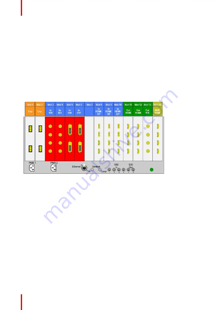
On the E2 model, the input cards occupy slots 3 through 10 and are right justified to slot 10.
On the S3
–
4K model, the input cards occupy slots 4 through 6 and are right justified to slot 6.
If there is an empty input slot between two input slots, all input cards to the left of the empty slot are marked
with red. Red indicates that although the cards will operate properly, inputs from these cards will not be
available at the Multiviewer.
Image 6-15: E.g. E2 with an empty input-card slot
If the card in the slot is wrong type (e.g. output card in input slot, or vice versa) then the slot in the diagram will
be greyed out.
Input Connector Grouping
The reason for connector grouping is that in order to accommodate higher resolutions with no loss of quality
bandwidth has to be added to the signalpath. By combining connectors a higher resolution all the way up to
4K@60Hz with progressive scan can be added with its full color space 4:4:4.
Several rules apply when defining an input configuration:
1.
An Input connector can only be assigned to one input configuration.
2.
Multiple input connectors in the same configuration must be of the same type and in the same slot or in
adjacent slots. For example, cannot have a HDMI connector and an SDI connector in the same input
configuration.
3.
An input can be configured from one, two, or four connectors.
4.
A multi
—
connector input is still ONE input.
5.
Maximum of 4 single link connectors can be assigned to an Input.
6.
Maximum of 8 single link connectors can be assigned to a background, Background.
7.
Maximum of 128 input configurations can be assigned.
Examples of 4K Valid Inputs:
Summary of Contents for Event Master E2 Series
Page 1: ...ENABLING BRIGHT OUTCOMES User s Guide Event Master Devices...
Page 12: ...R5905948 12 Event Master Devices 12...
Page 24: ...R5905948 12 Event Master Devices 24 Safety...
Page 52: ...R5905948 12 Event Master Devices 52 General...
Page 82: ...R5905948 12 Event Master Devices 82 Hardware orientation...
Page 102: ...R5905948 12 Event Master Devices 102 Front Panel Menu orientation...
Page 272: ...R5905948 12 Event Master Devices 272 Image 6 137 EM GUI orientation...
Page 304: ...R5905948 12 Event Master Devices 304 Updating firmware...
Page 326: ...R5905948 12 Event Master Devices 326 Image 9 28 General operation example...
Page 382: ...R5905948 12 Event Master Devices 382 Preventive maintenance actions...
Page 444: ...R5905948 12 Event Master Devices 444 E2 Maintenance...
Page 528: ...R5905948 12 Event Master Devices 528 EC 200 EC 210 Maintenance...
Page 569: ...569 R5905948 12 Event Master Devices Troubleshooting C...
Page 572: ...R5905948 12 Event Master Devices 572 Troubleshooting...


