Operation Theory
43
desired speed profile, thus making it is much easier for program-
mers, and mechnical or electrical engineers to discover the source
of a problem.
4.2
Motion Control Modes
Unlike motor control which is only for positive or negative moving,
motion control make the motors run according to a specific speed
profile, path trajectory and synchronous condition with other axes.
The following sections describe the motion control modes of this
controller.
4.2.1
Coordinate system
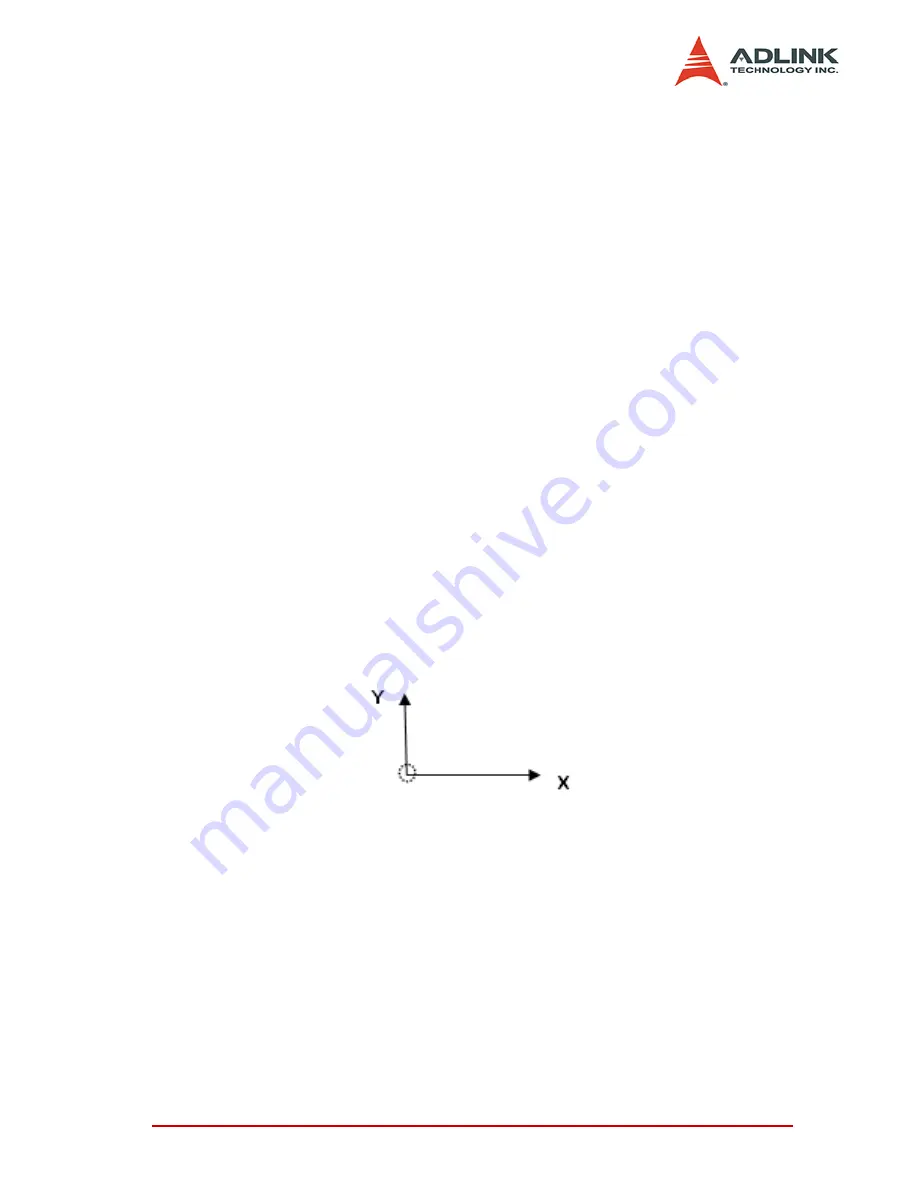
We use Cartesian coordinates and pulses for units of length. The
physical length depends on mechanical parts and a motor’s reso-
lution. For example, if users install a motor on a screw ball the
pitch of the screw ball is 10mm, and the pulses needed for a round
of motor are 10,000 pulses. We can say that one pulse’s physical
unit is equal to 10mm/10,000p =1 micro-meter.
Just set a command with 15,000 pulses for motion control if we
want to move 15mm. How about if we want to move 15.0001mm?
The motion controller will automatically keep the residue value
less than 1 pulse and add it to next command.
The motion controller sends incremental pulses to motor drivers.
Meaning that only relative commands can be sent to the motor
driver. However, an absolute command can be sent by first calcu-
lating the difference between current position and target position
and then sending the differences to the motor driver. For example,
if current position is 1000 and we want to move a motor to 9000,
the user can use an absolute command to set a target position of
9000 by adding on the command of +8000 pulses to the current
1000. The motion controller will send 8000 pulses to the motor
driver to move the position to 9000.
Summary of Contents for cPCI-8168
Page 4: ......
Page 10: ...vi List of Figures...
Page 29: ...Installation 19 2 9 Overview of CN3 CN6...
Page 31: ...Installation 21 2 11 Switch Setting...
Page 204: ...194 Function Library...


