64
Operation Theory
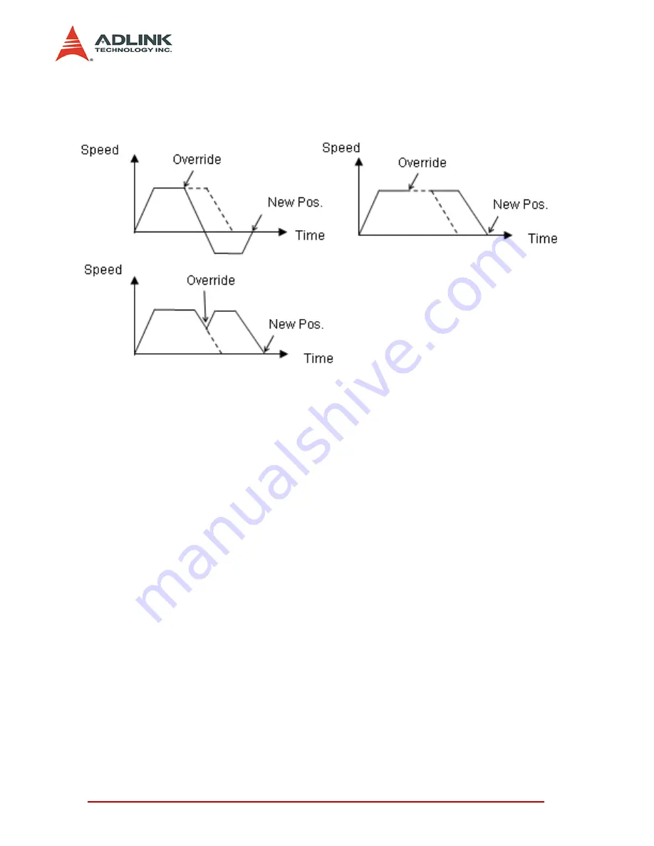
Notice that if the new target’s position’s relative pulses are smaller
than the original slow down pulses, this function can’t work prop-
erly.
4.3
The motor driver interface
We provide several dedicated I/Os which can be connected to the
motor driver directly and have their own functions. Motor drivers
have many kinds of I/O pins for an external motion controller to
use. We classify them in two groups. One is pulse I/O signals,
including pulse command and encoder interface. The other is digi-
tal I/O signals, including servo ON, alarm, INP, servo ready, alarm
reset and emergency stop inputs. The following sections will
describe the functions of these I/O pins.
4.3.1
Pulse Command Output Interface
The motion controller uses a pulse command to control servo/
stepper motors via motor drivers. To use the position command
function the drivers must be set to position mode. The pulse com-
mand consists of two signal pairs. It is defined as OUT and DIR
pins on a connector. Each signal has two pins as a pair for differ-
ential output. There are two signal modes for pulse output com-
mand: (1) single pulse output mode (OUT/DIR), and (2) dual pulse
output mode (CW/CCW type pulse output). The mode must be the
Summary of Contents for cPCI-8168
Page 4: ......
Page 10: ...vi List of Figures...
Page 29: ...Installation 19 2 9 Overview of CN3 CN6...
Page 31: ...Installation 21 2 11 Switch Setting...
Page 204: ...194 Function Library...


