background image


November, 2018 Rev.1.4 


37 

Data Pointer Register (DPTR) 

The Data Pointer (DPTR) is a 16-bit register which is used to form 16-

bit addresses for External Data Memory accesses (MOVX A, @DPTR and MOVX @DPTR, A), for 
program byte moves (MOVC A, @A+DPTR) and for indirect program jumps (JMP @A+DPTR). 

Two true 16-bit operations are allowed on the Data Pointer – load immediate (MOV DPTR, #data) and 
increment (INC DPTR). 

Program Status Word (PSW) 

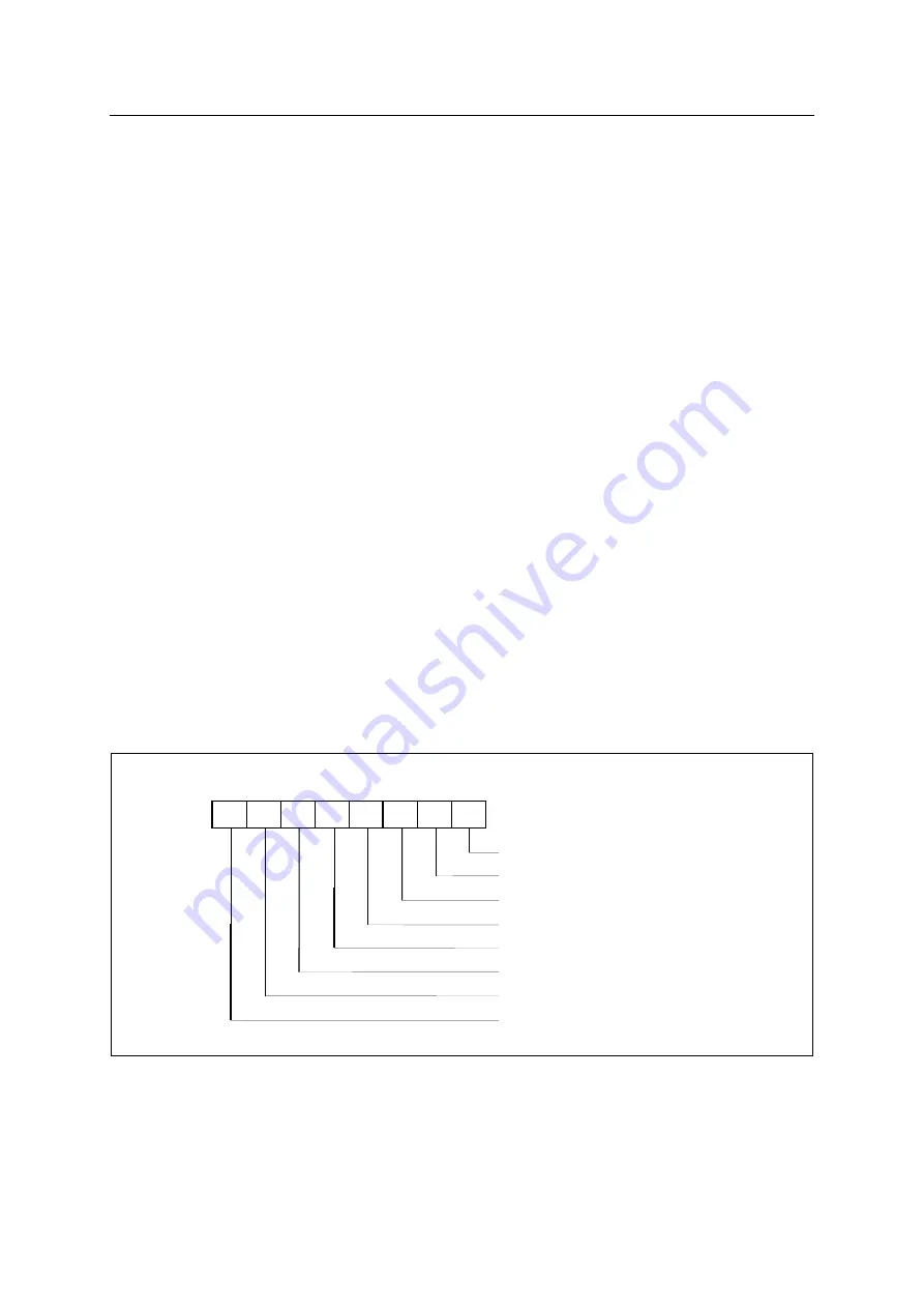
The PSW contains several status bits that reflect the current state of 

the CPU. The PSW, shown in Figure 8.1, resides in SFR space. It contains the Carry bit, the Auxiliary 
Carry (for BCD operations), the two register bank select bits, the Overflow flag, a Parity bit, and two 
user-definable status flags. 

CY

 The Carry bit, other than serving the function of a Carry bit in arithmetic operations, also serves as 

the “Accumulator” for a number of Boolean operations. 

AC

 The Auxiliary Carry bit, this bit is set when there is a carry from bit 3 of ALU or there is no borrow 

from bit 4 of ALU after operation. 

RS0, RS1

 The bits RS0 and RS1 are used to select one of the four register banks shown in Figure 

8.3. A number of instructions refer to these RAM locations as R0 through R7. The selection of which 
of the four banks is being referred to is made on the basis of the bits RS0 and RS1 at execution time. 

OV

 Overflow flag. This bit is set to “1” when an overflow occurs as the result of an arithmetic operation 

involving signs. An overflow occurs when the result of an addition or subtraction e127(7F

H

or 128(80

H

). The CLRV instruction clears the overflow flag. There is no set instruction. When the BIT 

instruction is executed, bit 6 of memory is copied to this flag. 

P

 The Parity bit reflects the number of 1s in the Accumulator: P=1 if the Accumulator contains an odd 

number of 1s, and P=0 if the Accumulator contains an even number of 1s. Thus the number of 1s in 
the Accumulator plus P is always even. 

Two bits in the PSW are uncommitted and may be used as general purpose status flags. 


Program Status Word


Parity Flag


User-definable Flag


ALU overflow Flag


Register Bank Select 0 Flag


Register Bank Select 1 Flag


General Purpose User-definable Flag


ALU Auxilliary Carry Flag


ALU Carry Flag


7


1


RS0  OV 

F1 

CY  AC 

F0  RS1 

Figure 8-4 PSW Register 

Summary of Contents for MC96FR364B

Page 1: ...MC96FR364B November 2018 Rev 1 4 1 ABOV SEMICONDUCTOR Co Ltd 8 BIT MICROCONTROLLERS MC96FR364B User s Manual Rev 1 4...

Page 2: ...ta register is changed from 9FH to C0H REVISION 1 2 January 8 2016 11 7 6 Examples of REMOUT control The function of rdpe_disable_mode_init is a prerequisite for RDPE disable mode REVISION 1 3 January...

Page 3: ...nductor offices in Korea or Distributors ABOV Semiconductor reserves the right to make changes to any information here in at any time without notice The information diagrams and other data in this man...

Page 4: ...ERATING CONDITION 24 7 3 VOLTAGE DROPOUT CONVERTER VDC CHARACTERISTICS 25 7 4 BROWN OUT DETECTOR BOD CHARACTERISTICS 25 7 5 POWER ON RESET CHARACTERISTICS 26 7 6 DC CHARACTERISTICS 26 7 7 AC CHARACTER...

Page 5: ...N IN SLEEP STOP BOD MODE 157 12 3 SLEEP mode 157 12 4 STOP mode 158 12 5 BOD mode 160 12 6 Register Map 161 12 7 Register Description 161 13 RESET 162 13 1 Overview 162 13 2 Reset source 162 13 3 Bloc...

Page 6: ...38 Figure 10 1 External Interrupt trigger condition 52 Figure 10 2 Block Diagram of Interrupt Controller 53 Figure 10 3 Sequence of Interrupt handling 55 Figure 10 4 Effective time of interrupt reques...

Page 7: ...de 102 Figure 11 27 Block Diagram of IR Capture function 107 Figure 11 28 Block Diagram of IR AMP 107 Figure 11 29 Block Diagram of Carrier Generator 111 Figure 11 30 Period of Carrier signal and Remo...

Page 8: ...d VDD Rises Slowly 164 Figure 13 5 Fuse Configuration Value Read Timing after Power On 164 Figure 13 6 Operation according to Power Level 165 Figure 13 7 Reset procedure due to external reset input 16...

Page 9: ...ity specialized for remote control application Additionally the MC96FR364B supports power saving modes to reduce power consumption NOTE1 In this document the ROM means non volitile memory which is rea...

Page 10: ...Execution Time 200ns 10MHz 1 Cycle NOP Instruction Power down mode SLEEP STOP mode Operating Frequency 1 12MHz Operating Voltage 1 75 3 6V 1 12MHz Operating Temperature 20 70 PKG Type 28 TSSOP Availab...

Page 11: ...11 1 3 1 Device Nomenclature Device nomenclature MC96FR364Bx Family Name Package type RoHS Packing MC96FR364Bx R B T R TSSOP Halogen Free T Tape Reel B X none MC96FR364B series MC96FR364BD series X D...

Page 12: ...monitoring etc OCD debugger program works on Microsoft Windows 7 NT 2000 XP Vista 32 bit operating system If you want to see details more please refer to OCD debugger manual You can download debugger...

Page 13: ...es PGMPlusLC II is low cost writing tool USB interface is supported No need for USB driver installation Connect to the external power adaptor 5V 2A Fast 32 bit Cortex M3 MCU is used Support high volta...

Page 14: ...rammer E GANG4 6 can program maximum4 6 MCUs at a time So it is mainly used in mass production line As gang programmer is standalone type it does not require host PC 2 VDD 4 GND 6 Serial Clock DSCL 8...

Page 15: ...SYSTEM CONTROL On Chip Debug M8051 CORE RAM 1792B 256B FLASH 64KB Power On Reset Brown Out Detector CARRIER GENERATOR P01 T1 PWM1 REMOUT P04 EC0 P00 T0 P02 T2 P03 PWM3 P36 P12 INT0 P37 P13 INT1 P21 P1...

Page 16: ...P02 KS2 T2 P01 KS1 T1 PWM1 P00 KS0 T0 P37 INT1 SS0 SDA P36 INT0 XCK0 SCL VSS XIN XOUT P20 RESETB P10 KS8 MOSI1 P11 KS9 MISO1 P12 KS10 INT0 P13 KS11 INT1 P14 KS12 SS1 INT2 P15 KS13 XCK1 INT3 P16 KS14 M...

Page 17: ...MC96FR364B November 2018 Rev 1 4 17 4 PACKAGE DIMENSION...

Page 18: ...MC96FR364B 18 November 2018 Rev 1 4 Figure 4 1 PKG DIMENSION 28 TSSOP...

Page 19: ...de by setting PxnOD bit in PxOD register Input KS8 MOSI1 P11 KS9 MISO1 P12 KS10 INT0 NOTE0 P13 KS11 INT1 NOTE0 P14 KS12 SS1 INT2 NOTE0 P15 KS13 XCK1 INT3 NOTE0 P16 KS14 MOSI0 P17 KS15 MISO0 P20 I O 3...

Page 20: ...resistor can be activated by setting PxnPU bit in PxPU register when this port is used as input port Can be configured as an open drain output mode by setting PxnOD bit in PxOD register Input SS0 EC2...

Page 21: ...DD LevelShift ExtVDD to 1 8V Px data PxOD open drain PxPU pull up selection SUB FUNC DATA OUTPUT PxIO direction SUB FUNC DIRECTION 0 1 MUX MUX 1 0 PORTx INPUT SUB FUNC DATA INPUT ANALOG CHANNEL ENABLE...

Page 22: ...PUT PxIO direction SUB FUNC DIRECTION 0 1 MUX MUX 1 0 PORTx INPUT SUB FUNC DATA INPUT ANALOG CHANNEL ENABLE ANALOG INPUT 0 1 MUX r D CP Q VDD EXTERNAL INTERRUPT INTERRUPT ENABLE EDGE REG FLAG CLEAR PO...

Page 23: ...MC96FR364B November 2018 Rev 1 4 23 6 3 REMOUT Port Data PAD VDD Figure 6 3 REMOUT port...

Page 24: ...r Absolute Maximum Ratings may cause permanent damage to the device This is a stress rating only and functional operation of the device at any other conditions beyond those indicated in the operationa...

Page 25: ...sumption mode 7 4 BROWN OUT DETECTOR BOD CHARACTERISTICS Parameter Symbol Condition MIN TYP MAX Unit Operating Voltage 1 5 3 6 V Operating Temperature 20 70 Detection Level VBODOUT0 NOTE 1 6 1 65 1 70...

Page 26: ...Unit Input Low Voltage VIL P0 P1 P2 P3 Schmitt Trigger Input 0 5 0 2VDD V Input High Voltage VIH P0 P1 P2 P3 Schmitt Trigger Input 0 8VDD VDD 0 5 V Output Low Voltage VOL P0 P1 P2 P3 IOL 10mA VDD 3 3...

Page 27: ...L Pulse Width tCPW XIN 40 ns External Clock Transition Time tRCP tFCP XIN 10 ns Interrupt Input Width tIW INT0 INT3 2 tSYS RESETB Input Pulse L Width tRST RESETB 8 us External Counter Input H or L Pul...

Page 28: ...Slave tLEAD tLEAD 0 5 tXCK 2 tSCLK 0 5 tXCK ns Lag time Master Slave tLAG tLAG 0 5 tXCK 2 tSCLK 0 5 tXCK ns Data setup time inputs Master Slave tSIM tSIS 2 2 2 2 tSCLK Data hold time inputs Master Sla...

Page 29: ...OM XCKx UCPOL 0 OUTPUT tXCKH tXCKL SS0 OUTPUT MSB LSB LSB MSB tSIM tHIM tDIS tLEAD tSOM BIT 6 1 BIT 6 1 XCK0 UCPOL 1 OUTPUT MOSI OUTPUT MISO INPUT tXCK 0 8VDD 0 2VDD tSOM XCK0 UCPOL 0 OUTPUT tXCKH tXC...

Page 30: ...DD tHIM XCKx UCPOL 0 INPUT tXCKH tXCKL SS0 INPUT MSB LSB LSB MSB tSOS tHOS tDIS tLEAD tSIM BIT 6 1 BIT 6 1 tLAG XCK0 UCPOL 1 OUTPUT MOSI OUTPUT MISO INPUT tXCK 0 8VDD 0 2VDD tHOM XCK0 UCPOL 0 OUTPUT t...

Page 31: ...PORT CHARACTERISTICS 0 5 10 15 20 25 30 VOH V 0 0 5 1 0 1 5 2 0 2 5 3 0 3 5 4 0 VDD 2V VDD 3V VDD 4V 6 5 4 3 2 1 0 0 0 5 1 0 1 5 2 0 2 5 3 0 3 5 4 0 VOL V IOL mA VDD 2V VDD 3V VDD 4V IOH mA Figure 7...

Page 32: ...ified operating range e g outside specified VDD range This is for information only and devices are guaranteed to operate properly only within the specified range The data presented in this section is...

Page 33: ...de in device 8 1 Program Memory A 16 bit program counter is capable of addressing up to 64K bytes The following figure shows a map of program memory in MC96FR364B After reset the CPU begins program ex...

Page 34: ...rouped into 4 banks of 8 registers Program instructions call out these registers as R0 through R7 Two bits in the Program Status Word PSW select which register bank is in use This allows more efficien...

Page 35: ...ect addressing can be divided into 3 segments as listed below and shown in Figure 8 3 Register Bank 0 3 Locations 00H through 1FH 32 bytes ASM 51 and the device after reset default to register bank 0...

Page 36: ...Program Counter PC Accumulator A B register B the Stack Pointer SP the Program Status Word PSW general purpose register R0 R7 and DPTR Data pointer register NOTE There s some address space in the SFRs...

Page 37: ...nd RS1 are used to select one of the four register banks shown in Figure 8 3 A number of instructions refer to these RAM locations as R0 through R7 The selection of which of the four banks is being re...

Page 38: ...gh 06FFH This address space is assigned to XDATANOTE region and used for data storage NOTE XRAM 64Bytes of page buffers and some eXtended SFR XSFR are assigned to XDATA area in MC96FR364B And these ad...

Page 39: ...T3DRL PW M3PRL T3DRH PW M3PRH T2L T2DRL CDR2L C0H P3 P0PC 0000_0000 RDBH RDBL RDRH RDRL T2CR T2H T2DRH CDR2H B8H IP 00_0000 RDCH CFRH CFRL RDCL RODR ROB B0H P2IO _ 000 T0CR T0 CDR0 T0 DR T1CR T1DR PW...

Page 40: ...1B PBUF_1C PBUF_1D PBUF_1E PBUF_1F 8010H PBUF_10 PBUF_11 PBUF_12 PBUF_13 PBUF_14 PBUF_15 PBUF_16 PBUF_17 8008H PBUF_08 PBUF_09 PBUF_0A PBUF_0B PBUF_0C PBUF_0D PBUF_0E PBUF_0F 8000H PBUF_00 PBUF_01 PBU...

Page 41: ...1 0 B R W R W R W R W R W R W R W R W Initial value 00H B B Register SP Stack Pointer 81H 7 6 5 4 3 2 1 0 SP R W R W R W R W R W R W R W R W Initial value 07H SP Stack Pointer DPL Data Pointer Low Byt...

Page 42: ...ACC Set by hardware to 1 if it contains an odd number of 1s otherwise it is reset to 0 EO Extended Operation Register A2H 7 6 5 4 3 2 1 0 TRAP_EN DPSEL 2 DPSEL 1 DPSEL 0 R R R R W R R W R W R W Initia...

Page 43: ...sistor is activated If PxnPU is written logic zero the pull up resistor is deactivated When the port is configured as an input port internal pull up is deactivated regardless of the PxnPU bit After re...

Page 44: ...rupt Enable Register P1 88H R W 00H P1 Data Register P1IO A0H R W 00H P1 Direction Register P1PU 2F01H R W 00H P1 Pull up Resistor Selection Register P1OD 2F09H R W 00H P1 Open drain Selection Registe...

Page 45: ...W R W R W Initial value 00H P0PU 7 0 P0 Pull up Control 0 Disable pull up 1 Enable pull up P0OD P0 Open drain Selection Register 2F08H 7 6 5 4 3 2 1 0 P07OD P06OD P05OD P04OD P03OD P02OD P01OD P00OD...

Page 46: ...W R W R W R W R W R W R W Initial value 00H P1 7 0 I O Data P1IO P1 Direction Register A0H 7 6 5 4 3 2 1 0 P17IO P16IO P15IO P14IO P13IO P12IO P11IO P10IO R W R W R W R W R W R W R W R W Initial value...

Page 47: ...itial value 00H P2 2 0 I O Data P2IO P2 Direction Register B0H 7 6 5 4 3 2 1 0 P22IO P21IO P20IO R W R W R W Initial value 00H P2IO 2 0 P2 Direction NOTE1 0 Input 1 Output P2PU P2 Pull up Resistor Sel...

Page 48: ...ster 2F52H 7 6 5 4 3 2 1 0 P22BPC P21BPC P20BPC R W R W R W Initial value 00H P2BPC 2 0 Control port direction and use of internal pull up resistor when external VDD drops below VBODOUT0 level 0 Maint...

Page 49: ...d use of internal pull up resistor when external VDD drops below VBODOUT0 level 0 Maintain its previous state input or output 1 Changed to input port and pull up resistor is activated PSR0 Port Select...

Page 50: ...s triggered on P14 INT1SWAP Select the source of External Interrupt 1 0 External Interrupt 1 is triggered on P37 1 External Interrupt 1 is triggered on P13 INT0SWAP Select the source of External Inter...

Page 51: ...o 6 groups and each group can have different priority according to IP and IP1 registers By default all interrupt sources are level triggered but external interrupts can be set to operate in edge trigg...

Page 52: ...nd is configured as level triggered the interrupt will trigger as long as the pin is held low or high External interrupts are detected asynchronously This implies that these interrupts can be used for...

Page 53: ...13 14 15 16 17 18 19 20 21 22 23 0 1 2 3 4 5 6 7 8 9 10 11 12 13 14 15 16 17 18 19 20 21 22 23 0 1 2 3 4 5 6 7 8 9 10 11 12 13 14 15 16 17 18 19 20 21 22 23 0 1 2 3 4 5 6 7 8 9 10 11 12 13 14 15 16 17...

Page 54: ...le 007BH T3 INT16 IE2 4 17 Maskable 0083H I2C INT17 IE2 5 18 Maskable 008BH REMOCON INT18 IE3 0 19 Maskable 0093H KEYSCAN INT19 IE3 1 20 Maskable 009BH WT INT20 IE3 2 21 Maskable 00A3H WDT INT21 IE3 3...

Page 55: ...t Request To activate interrupt request from interrupt sources both EA bit in IE register and individual enable bit INTnE in IEx register must be enabled At this time the effective time of interrupt r...

Page 56: ...and the interrupt handler should allow another interrupt request The following example shows how to allow INT0 interrupt request while executing INT1 interrupt service routine In this example INT0 has...

Page 57: ...interrupts are requested at the same time the one of highest priority is serviced first 10 8 Interrupt Service Procedure 10 9 Generation of Branch Address to Interrupt Service Routine ISR The followi...

Page 58: ...bit CLP2 CLP1 C2P1 C1P1 C2P2 C1P2 CLP2 Interrupt sampled here 8 bit interrupt Vector INT_SRC INTR_ACK LAST_CYC INTR_LCALL INT_VEC PROGA SCLK 8 h00 INT_VEC NOTE Main Task Saving Register Restoring Reg...

Page 59: ...enable bits INTnE Each IE1 IE2 and IE3 register only has 6 individual interrupt enable bits Totally 16 peripheral and external interrupts are controlled by these registers 10 12 3 Interrupt Priority R...

Page 60: ...pin 10 12 6 External Interrupt Polarity Register EIPOLA This register has different meaning according to the value set in EIEDGE register When a external interrupt is configured to be triggered by a l...

Page 61: ...disable External Interrupt 2 0 Disable 1 Enable INT2E Enable or disable External Interrupt 1 0 Disable 1 Enable INT1E Enable or disable External Interrupt 0 0 Disable 1 enable INT0E Reserved 0 Disabl...

Page 62: ...0 Disable 1 Enable INT14E Enable or disable Timer 1 Interrupt 0 Disable 1 Enable INT13E Enable or disable Timer 0 Interrupt 0 Disable 1 enable INT12E Enable or disable USART RX1 Interrupt 0 Disable 1...

Page 63: ...1 priority 1 0 Group x is of level 2 priority 1 1 Group x is of level 3 priority highest EIFLAG External Interrupt Flag Register ACH 7 6 5 4 3 2 1 0 FLAG3 FLAG2 FLAG1 FLAG0 R R R R R W R W R W R W In...

Page 64: ...7 6 5 4 3 2 1 0 POLA3 POLA2 POLA1 POLA0 R W R W R W R W R W R W R W R W Initial value 00H POLA 3 0 Selects the trigger level of external interrupt high or log level When configured as level trigger mo...

Page 65: ...of the divided clocks is used as internal operating clock SCLK according to the DIV 1 0 bits in SCCR register By default frequency of SCLK is same as that of XINCLK ie divided by 1 11 1 2 Block Diagr...

Page 66: ...abled at stop mode 1 Ring Oscillator is enabled at stop mode DIV 1 0 Selects the divide ratio of main oscillator operating clock XIN DIV1 DIV0 Description in case of fXIN 8MHz 0 0 fXIN 1 8MHz 0 1 fXIN...

Page 67: ...ator regardless of BCK 2 0 BIT is a 8 bit binary counter and has the following features Guarantees the oscillation stabilization time when a power on or reset occurs Guarantees the oscillation stabili...

Page 68: ...e runs 1 BIT counter is cleared and counter re starts PRD 2 0 Selects BIT interrupt interval When BIT counter reaches to the value listed below an interrupt may be issued The BIT interrupt period is s...

Page 69: ...November 2018 Rev 1 4 69 Initial value 00H BIT 7 0 BIT counter value...

Page 70: ...TOP modeNOTE and also as a general system timer One example is to limit the maximum time allowed for certain operations giving an interrupt when the operation has run longer than expected In System Re...

Page 71: ...e WDTR should be greater than 01H WDTCR Watch Dog Timer Counter Register Read Case 8EH 7 6 5 4 3 2 1 0 WDTCR7 WDTCR6 WDTCR5 WDTCR4 WDTCR3 WDTCR2 WDTCR1 WDTCR0 R R R R R R R R Initial value 00H WDTCR 7...

Page 72: ...1 WDT interrupt occurred 11 3 5 WDT Interrupt Timing Source Clock BIT Overflow WDTCR 7 0 WDTR 7 0 WDTIF Interrupt WDTRESETB WDTCL Occur WDTR 0000_0011b Match Detect Counter Clear RESET 0 1 2 3 0 1 2 3...

Page 73: ...enerated on INT0 or INT1 pins In 8 16 bit Timer Counter Mode Timer 0 compares counter value with the value in timer data register and when counter reaches to the compare value the timer output is togg...

Page 74: ...o is decided by T0CK 2 0 and T1CK 2 0 bits When the external clock EC0 is selected as a clock source the counter increases at rising edge of the clock When the counter value of each 8 bit timer matche...

Page 75: ...DR Occur Interrupt Occur Interrupt Occur Interrupt T0DR T1DR Value TIME STOP Timer 0 1 T0IF T1IF Interrupt Occur Interrupt Occur Interrupt Clear Start Disable Enable Up count T0ST T1ST Start Stop T0ST...

Page 76: ...de timer output is toggled and appears on P01 port whenever T1 T0 matches T1DR T0DR The initial value of each timer s output is 0 and output frequency is calculated by the following equation 1 Value P...

Page 77: ...cleared to 00H and counts up again The timer interrupt in Capture Mode is very useful when the interval of capture event on port P36 P37 is longer than the interrupt period of timer That is by countin...

Page 78: ...Register T0EN T0CN Clear B3H T0ST T0CK 2 0 3 T1CK 1 0 2 INT0 EIEDGE 1 0 B5H INT1IF INT1 Interrupt 8 bit Timer1 Counter T1 8 bit 8 bit Timer1 Data Register CDR1 8 bit T1CN Clear B6H T1ST INT1 EIEDGE 3...

Page 79: ...T0F T1F FFH FFH YYH 00H 00H 00H 00H 00H T0 T1 Value Interrupt Request INT0F INT1F TIME 1 2 3 4 5 6 n 2 n 1 n Interrupt Interval Period 0 Count Pulse Period PCP Up count CDR0 CDR1 Load Ext INT0 PIN Fig...

Page 80: ...register To output the PWM waveform through T1 PWM1 pin the T1_PE bit in PWM1HR register is to be set The period and duty of PWM waveform are decided by PWM1PR PWM Period Register PWM1DR PWM Duty Regi...

Page 81: ...or duty value In other case PWM waveform is low for duty value P r e s c a l e r MUX T0 Clock Source SCLK T1CN T1ST T1CK 1 0 2 1 2 16 8 bit Timer1 PWM Period Register 8 bit Timer1 Counter 2 bit Clear...

Page 82: ...12us Duty Cycle 1 05H X2us 12us Duty Cycle 1 05H X2us 12us Period Cycle 1 0EH X2us 32us 31 25KHz Period Cycle 1 0AH X2us 22us 45 5KHz Write 0AH to PWM1PR T1CR 1 0 10H 2us PWM1HR 00H PWM1PR 0EH PWM1DR...

Page 83: ...mer 0 output or not through I O pin 0 Timer 0 output does not come out through I O pin 1 Timer 0 output overrides the normal port functionality of I O pin CAP0 Selects operating mode of Timer 0 0 Time...

Page 84: ...W R W R W R W R W R W R W R W Initial value 00H POL Selects polarity of PWM 0 PWM waveform is low for duty value 1 PWM waveform is high for duty value 16BIT Selects width of Timer 0 1 0 Timer 0 1 are...

Page 85: ...egister Read Case B6H 7 6 5 4 3 2 1 0 T17 T16 T15 T14 T13 T12 T11 T10 R R R R R R R R Initial value 00H T1 7 0 T1 Counter value PWM1DR Timer 1 PWM Duty Register Write Case B6H 7 6 5 4 3 2 1 0 T1PD7 T1...

Page 86: ...can detect the envelope of IR input signal or counts the number of input carrier signal In envelop detection mode of operation the counter value of Timer 2 is captured into timer capture register on f...

Page 87: ...P r e s c a l e r MUX 1 2 4 8 SCLK T2CK 2 0 3 256 EC2 or IRSensor EC2E 1 CRF T2EDGE 1 0 T2IF WTIF T2 or WT Interrupt WT Out IRCAP2 IRCAP2 T2EDGE 1 0 00B 0 1 64 16 P r e s c a l e r MUX 1 2 4 8 SCLK C...

Page 88: ...enabled by setting T2IR bit in IRCC2 register This mode of operation is only available when IRCEN bit in IRCC1 register is set The clock source is the rising edge of input carrier signal Like output...

Page 89: ...2 is a normal counter 1 Timer 2 is an event counter clocked by EC2 T2_PE Controls whether to output Timer 2 output or not through I O pin 0 Timer 2 output does not come out through I O pin 1 Timer 2 o...

Page 90: ...R2L2 CDR2L1 CDR2L0 R R R R R R R R Initial value 00H CDR2L 7 0 T2 Capture Data Low T2H Timer 2 Counter High Read Case C7H 7 6 5 4 3 2 1 0 T2H7 T2H6 T2H5 T2H4 T2H3 T2H2 T2H1 T2H0 R R R R R R R R Initia...

Page 91: ...input normally amplified carrier signal and overflow of WT When Timer 3 is used to calculate the number of carrier signal the rising edge of input carrier becomes the clock source of Timer 3 For more...

Page 92: ...ge or both edge When Timer 3 operates in IR capture mode the capture source becomes the output of IR AMP And the T3EDGE 1 0 bits in IRCC2 register select the triggering condition of Watch Timer output...

Page 93: ...if enabled EC3E PWM3 E CAP3 T3CK2 T3CK1 T3CK0 T3CN T3ST T3CR X X 1 X X X X X ADDRESS CAH INITIAL VALUE 0000_0000B CCH INT3IF INT3 Interrupt 16 bit Counter 16 bit Capture Register T3CN Clear CBH T3ST I...

Page 94: ...ns T3CK 2 0 001 500ns T3CK 2 0 011 2us 16 bit 60 938Hz 30 469Hz 7 617Hz 15 bit 121 87Hz 60 938Hz 15 234Hz 10 bit 3 9KHz 1 95KHz 0 49KHz 9 bit 7 8KHz 3 9KHz 0 98KHz 8 bit 15 6KHz 7 8KHz 1 95KHz Table 1...

Page 95: ...P03 PWM3 1 2 4 8 16 64 256 CRF P r e s c a l e r SCLK T3REQ T2REQ T0REQ T3_PE POL T1REQ Figure 11 22 Block Diagram of Timer 3 in PWM Mode T3CN T3ST 16 bit Timer3 PWM Period Register 16 bit Timer3 Coun...

Page 96: ...d by PWM3PRH and PWM3PRL registers and the duty of PWM3 is decided by PWM3DRH and PWM3DRL registers PWM3PRH and PWM3PRL registers are write only Note that the value of period and duty registers can be...

Page 97: ...mer 3 0 Timer 3 is Normal Timer Counter 1 Timer 1 is PWM CAP3 Selects operating mode of Timer 3 0 Timer Counter mode 1 Capture mode T3CK 2 0 Selects the clock source of Timer 3 NOTE T3CK2 T3CK1 T3CK0...

Page 98: ...ing 0 to this bit position clears interrupt flag of each timer T3L Timer 3 Counter Low Read Case CBH 7 6 5 4 3 2 1 0 T3L7 T3L6 T3L5 T3L4 T3L3 T3L2 T3L1 T3L0 R R R R R R R R Initial value 00H T3L 7 0 T...

Page 99: ...3DRL5 T3DRL4 T3DRL3 T3DRL2 T3DRL1 T3DRL0 W W W W W W W W Initial value FFH T3DRL 7 0 T3 Compare Data Low NOTE Be sure to clear PWM3E in T3CR register before loading this register PWM3PRL PWM3 Period R...

Page 100: ...ember 2018 Rev 1 4 7 6 5 4 3 2 1 0 P3PPH7 P3PPH6 P3PPH5 P3PPH4 P3PPH3 P3PPH2 P3PPH1 P3PPH0 W W W W W W W W Initial value FFH P3PPH 7 0 PWM3 Period High NOTE Writing is effective only when PWM3E 1 and...

Page 101: ...R0 registers To read each WTDRH WTDR1 and WTDR0 returns WT_TMR high 6 bit of WTIR and low 8 bit of WTIR counter value When Watch timer operates in IR capture mode the WT is a simple 14 bit up counter...

Page 102: ...capture0 capture2 WT Sync start WT clear WT clear WT clear WT clear WT clear WT clear WT Overflow WT stop Timer2 captures when T2EDGE 1 1 Timer3 captures when T3EDGE 1 1 SENSOR Input P31 WTIR Counter...

Page 103: ...6 5 4 3 2 1 0 WTEN OVFDIS WTCL WTCK1 WTCK0 R W R W R W R W R W Initial value 00H WTEN Enable Watch Timer 0 Disable WT 1 Enable WT OVFDIS Control auto clear function of WT when counters overflow NOTE1...

Page 104: ...upt flag of WT This flag bit is cleared when the interrupt is serviced or by writing 0 to this bit field 0 No WT interrupt is generated 1 WT interrupt occurred WTDRH Watch Timer Data Register High DCH...

Page 105: ...1L Watch Timer Capture Register 1 Low F4H 7 6 5 4 3 2 1 0 WTCR107 WTCR106 WTCR105 WTCR104 WTCR103 WTCR102 WTCR101 WTCR100 R R R R R R R R Initial value FFH WTCR1 7 0 When WT is in IR capture mode the...

Page 106: ...s 0 or second rising edge when PHASE bit is 1 of input carrier signal This register is initialized by setting WTCL bit in WTMR The WT interrupt is requested only when overflow condition occurs That is...

Page 107: ...mer 3 can support IR capture feature Both Timer 2 and Timer 3 can detect the envelop of incoming carrier or count the number of input carrier signal according to the setting of IRCC2 register 11 6 2 B...

Page 108: ...REFSEL Select external reference voltage as a input of IR AMP module 0 Internally divided voltage becomes reference voltage 1 External input voltage becomes reference voltage RSEL 2 0 Select referenc...

Page 109: ...lling Rising edge IRCC2 IR Capture Register 2 DFH 7 6 5 4 3 2 1 0 T3IR T2IR T3EDGE1 T3EDGE0 T2EDGE1 T2EDGE0 R W R W R W R W R W R W Initial value 00H T3IR Make T3 to calculate the number of incoming c...

Page 110: ...ng for Timer 2 and 3 for IR capture features IRCEN CAP2 3 T2 3 IR T2 3 EDGE 1 0 Timer 2 3 Operating Mode 0 0 0 XX Normal 16 bit Counter 0 1 X 00 Normal 16 bit Capture 1 1 X 01 10 11 IR Capture Envelop...

Page 111: ...pulse generation RDC reaches to RDRH or RDRLNOTE In this case the RDPE bit in RMR should be 1 At each match event an interrupt can be issued The RODR register can also be altered by writing to this re...

Page 112: ...Register E8H 7 6 5 4 3 2 1 0 RDIF CEN CCK1 CCK0 RDPE RDCK2 RDCK1 RDCK0 R R W R W R W R W R W R W R W Initial value 00H RDIF Interrupt flag This flag is cleared when the interrupt is serviced RDPE bit...

Page 113: ...R W R W R W R W R W Initial value FFH CFH 7 0 Carrier Frequency High Carrier High Interval CFH 7 0 X TCR_CLK TCR_CLK is the period of clock source for CRC counter selected by CCK 1 0 CFRL Carrier Freq...

Page 114: ...elected by RDCK 2 0 RDRL Remocon Data Register Low C5H 7 6 5 4 3 2 1 0 RDR15 RDR14 RDR13 RDR12 RDR11 RDR10 RDR9 RDR8 R W R W R W R W R W R W R W R W Initial value FFH RDR 7 0 Remote Data Low Lower byt...

Page 115: ...In this way four kinds of signal muxing is supported using carrier signal and RODR value The period and frequency of carrier signal and remote data pulse is calculated by the following equation The w...

Page 116: ...s and below figure is apparent ROB 0 or 1 RDRH RDRL RDRH Match with RDRH RDRL REMOUT ROD R tDH tDL Remocon Interrupt RDC tDH tDL Min 0 5us Max 32 64ms 4MHz RDPE RODR 01H RODR 00H RODR 01H ROB 0 or 1 R...

Page 117: ...e RDC counter functions when RDPE bit is 1 the interrupt is requested only when RDPE bit is 1 Even if the interrupt is not required to be serviced by CPU the flag can be read through RMR register And...

Page 118: ...24H 25H 26H 27H 28H 29H 2AH 2BH 2CH 2DH 2EH 2FH 30H 31H 32H 33H 34H 35H 36H 37H 38H 39H 3AH 3BH 3CH 3DH 3EH 3FH 20H 21H 22H 23H 24H 25H 26H 27H 28H 29H 2AH 2BH 2CH 2DH 2EH 2FH 30H 31H 32H 33H 34H 35H...

Page 119: ...sources The key interrupt triggering mode is selected by KITSR register 11 8 2 Block Diagram Internal Key Scan Interrupt 0 1 SRLC07 P07 SMRR07 KS7 0 1 SRLC00 P00 SMRR00 KS0 0 1 SRLC17 P17 SMRR17 KS15...

Page 120: ...al value 00H SMRR0 7 0 Enables key function of Port 0 pins 0 Key function is not used 1 Key function overrides the normal port functionality of I O pin SMRR1 Standby Mode Release Register 1 D3H 7 6 5...

Page 121: ...W R W R W Initial value 00H SRLC1 7 0 Selects the trigger level of key input interrupt when Port 1 is used as key input source 0 Triggered by a low level 1 Triggered by a high level KITSR Key Interrup...

Page 122: ...RX Complete Double Speed Asynchronous Communication Mode USART has three main parts of Clock Generator Transmitter and Receiver The Clock Generation logic consists of synchronization logic for extern...

Page 123: ...UMSEL1 UMSEL0 UPM1 UPM0 USIZE2 USIZE1 USIZE0 UCPOL UCTRLx1 ADDRESS E2H FAH INITIAL VALUE 0000_0000B UDRIE TXCIE RXCIE WAKEIE TXE RXE USARTEN U2X UCTRLx2 ADDRESS E3H FBH INITIAL VALUE 0000_0000B MASTE...

Page 124: ...UCTRL2 register The MASTER bit in UCTRL2 register controls whether the clock source is internal Master mode output port or external Slave mode input port The XCK pin is only active when the USART ope...

Page 125: ...sed as either clock input slave or clock output master The dependency between the clock edges and data sampling or data change is the same The basic principle is that data input on RXD MISO in spi mod...

Page 126: ...ble combinations of the frame formats Bits inside brackets are optional 1 data frame consists of the following bits Idle No communication on communication line TXD RXD St Start bit Low Dn Data bits 0...

Page 127: ...buffer UDATA register 11 9 8 2 Transmitter flag and interrupt The USART Transmitter has 2 flags which indicate its state One is USART Data Register Empty UDRE and the other is Transmit Complete TXC Bo...

Page 128: ...op bit means that a complete serial frame is present in the receiver shift register and the contents of shift register are to be moved into the receive buffer The receive buffer is read by reading the...

Page 129: ...bit from the received serial frame 11 9 9 4 Disabling Receiver In contrast to Transmitter disabling the Receiver by clearing RXE bit makes the Receiver inactive immediately When the Receiver is disab...

Page 130: ...le Speed mode If more than 2 samples have low levels the received bit is considered to a logic 0 and more than 2 samples have high levels the received bit is considered to a logic 1 The data recovery...

Page 131: ...ility to other SPI devices 11 9 10 1 SPI Clock Formats and Timing To accommodate a wide variety of synchronous serial peripherals from different manufacturers the USART has a clock polarity bit UCPOL...

Page 132: ...T shifts the second data bit value out to the MOSI and MISO outputs of the master and slave respectively Unlike the case of UCPHA 1 when UCPHA 0 the slave s SS input must go to its inactive high level...

Page 133: ...o that of synchronous or asynchronous operation An SPI transfer is initiated by checking for the USART Data Register Empty flag UDRE 1 and then writing a byte of data to the UDATA Register Caution In...

Page 134: ...SPI Mode UPM 1 0 Selects Parity Generation and Check methods UPM1 UPM0 Parity mode 0 0 No Parity 0 1 Reserved 1 0 Even Parity 1 1 Odd Parity USIZE 2 0 When in asynchronous or synchronous mode of oper...

Page 135: ...e polling 1 When TXC is set request an interrupt RXCIE Interrupt enable bit for Receive Complete 0 Interrupt from RXC is inhibited use polling 1 When RXC is set request an interrupt WAKEIE Interrupt e...

Page 136: ...s 1 USTATx USART0 1 Status Register E5H FDH 7 6 5 4 3 2 1 0 UDRE TXC RXC WAKE SOFTRST DOR FE PE R W R W R W R W R W R R R Initial value 80H UDRE The UDRE flag indicates if the transmit buffer UDATA is...

Page 137: ...E function of USART is used as a release source from STOP mode it is required to clear this bit in the RX interrupt service routine Else the device will not wake up from STOP mode again by the change...

Page 138: ...191 0 0 103 0 2 207 0 2 191 0 0 4800 47 0 0 95 0 0 51 0 2 103 0 2 95 0 0 191 0 0 9600 23 0 0 47 0 0 25 0 2 51 0 2 47 0 0 95 0 0 14 4K 15 0 0 31 0 0 16 2 1 34 0 8 31 0 0 63 0 0 19 2K 11 0 0 23 0 0 12 0...

Page 139: ...4 139 76 8K 6 7 0 12 0 2 8 0 0 17 0 0 11 0 0 23 0 0 115 2 K 3 8 5 8 3 5 5 0 0 11 0 0 7 0 0 15 0 0 230 4 K 1 8 5 3 8 5 2 0 0 5 0 0 3 0 0 7 0 0 250K 1 0 0 3 0 0 2 7 8 5 7 8 3 7 8 6 5 3 0 5M 1 0 0 2 7 8...

Page 140: ...on Up to 400 KHz data transfer speed 7 bit address Support two slave addresses Both master and slave operation Bus busy detection 11 10 2 Block Diagram SDA F F 8 bit Shift Register SHFTR Slave Addr Re...

Page 141: ...A low to high transition on the SDA line while SCL is high defines a STOP P condition START and STOP conditions are always generated by the master The bus is considered to be busy after START conditio...

Page 142: ...the slave And also when a slave addressed by a master is unable to receive more data bits the slave receiver must release the SDA line Data Packet The master can then generate either a STOP condition...

Page 143: ...lock HIGH period A master may start a transfer only if the bus is free Two or more masters may generate a START condition Arbitration takes place on the SDA line while the SCL line is at the HIGH leve...

Page 144: ...ow to handle interrupt and ACK signal When the START bit is set 8 bit data in I2CDR is transmitted out according to the baud rate 6 This is ACK signal processing stage for address packet transmitted b...

Page 145: ...a transfer because slave can receive more data from master In this case load data to transmit to I2CDR 2 Master stops data transfer even if it receives ACK signal from slave In this case set the STOP...

Page 146: ...SCL line is held low Interrupt after stop command P Arbitration lost as master and addressed as slave LOST Other master continues Slave Receiver 0x1D or Transmitter 0x1F Master Receiver SLA W ACK DATA...

Page 147: ...go to appropriate section In this stage I2C holds the SCL LOW This is because to decide whether I2C continues serial transfer or stops communication The following steps continue assuming that I2C doe...

Page 148: ...een master and slave is over To clear I2CSR write arbitrary value to I2CSR After this I2C enters idle state The processes described above for master receiver operation of I2C can be depicted as the fo...

Page 149: ...n Else if the address equals to SLA bits and the ACKEN bit is enabled I2C generates SSEL interrupt and the SCL line is held LOW Note that even if the address equals to SLA bits when the ACKEN bit is d...

Page 150: ...x46 P 0x22 IDLE IDLE Y GCALL 0x1F 0x97 0x17 From master to slave Master command or Data Write From slave to master 0xxx Value of Status Register ACK Interrupt SCL line is held low Interrupt after stop...

Page 151: ...bit is enabled I2C generates SSEL interrupt and the SCL line is held LOW Note that even if the address equals to SLA bits when the ACKEN bit is disabled I2C enters idle state When SSEL interrupt occur...

Page 152: ...er I2CSAR A6H R W 00H I2 C Slave Address Register I2CSAR1 A7H R W 00H I2 C Slave Address Register 1 Table 11 19 Register map of I2C SLA W ACK DATA LOST S or Sr Y N 0x45 ACK STOP Y N 0x44 P 0x20 IDLE I...

Page 153: ...I2 C is active RESET Initialize internal registers of I2 C 0 No operation 1 Initialize I2 C auto cleared INTEN Enable interrupt generation of I2 C 0 Disable interrupt operates in polling mode 1 Enable...

Page 154: ...cted Note 1 0 No STOP condition is detected 1 STOP condition is detected SSEL This bit is set when I2 C is addressed by other master Note 1 0 I2 C is not selected as slave 1 I2 C is addressed by other...

Page 155: ...I2C in master mode fI2C is calculated by the following equation fI2C 1 tSCLK 4 SCLL SCLH 4 I2CSDAHR SDA Hold Time Register A3H 7 6 5 4 3 2 1 0 SDAH7 SDAH6 SDAH5 SDAH4 SDAH3 SDAH2 SDAH1 SDAH0 R W R W...

Page 156: ...call address or not when I2 C operates in slave mode 0 Ignore general call address 1 Allow general call address I2CSAR1 I2 C Slave Address Register 1 A7H 7 6 5 4 3 2 1 0 SLA17 SLA16 SLA15 SLA14 SLA13...

Page 157: ...ntinuously Stop Stop USART Operates Continuously Stop Stop BOD Enabled Disabled Enabled Main OSC 1 12MHz Oscillation Stop Stop I O Port Retain Retain Retain or Input pull up mode Control Register Reta...

Page 158: ...here re three kinds of reset sources which can be used to release STOP mode power on reset nPOR external reset P20 and BOD reset As main oscillator stops oscillation in STOP mode WDT reset cannot be g...

Page 159: ...e kinds of interrupts are an external interrupt key input or MISO RXD pin in UART mode When an interrupt is detected the wake up logic enables BOD to check the external voltage level If the voltage le...

Page 160: ...STOP mode But there are 3 different points as follows First on entering BOD mode the I O ports can be set input ports with pull up registers on if PxBPC registers are not altered from reset value Sec...

Page 161: ...3H Enters STOP mode NOTE 1 Write PCON register 01H or 03H to enter SLEEP or STOP mode 2 When mode exit from STOP or SLEEP is done successfully the PCON register is auto cleared VDD Low BOD mode VDD ri...

Page 162: ...et is asserted 13 2 Reset source Reset can be caused by a power on reset nPOR event configuration reset by software watchdog overflow voltage drop detection by BOD OCD command or by assertion of an ex...

Page 163: ...t pin P20 is ignored by the dedicated noise canceller To have an effect as a reset source P20 port should be maintained low continuously at least 8us of time TRNC in typical condition The TRNC may var...

Page 164: ...03 00 01 02 F1 F2 F1 FE FF 00 01 02 03 External reset has no effect on counter value for configuration read Counting for config read start after POR is released H VDD nPOR Internal Signal Internal RES...

Page 165: ...section VDD must rise above flash operating voltage TXIN is period of XIN Slew Rate 0 025V ms Configuration value read point Around 1 5V 1 6V Config value is determined by writing option Rising secti...

Page 166: ...e in case external clock frequency is 8MHz For 5 clock periods from the point internal reset is released an initialization procedure is performed Thereafter the user program is executed from the addre...

Page 167: ...e the whole system to be reset but signals main chip to enter BOD STOP mode instantaneously For more information about BOD stop refer to section 12 4 POWER MANAGEMENT Besides BOD stop level the BOD gi...

Page 168: ...LS1 BODLS0 BODEN R W R W R W R W R W R W R W R W Initial value 81H PORF Power on reset or software reset event NOTE 0 No POR event detected after clear 1 POR occurred EXTRF External Reset Event NOTE V...

Page 169: ...7 6 5 4 3 2 1 0 BODIF BODOUT4 BODOUT3 BODOUT2 BODOUT1 R R R R R Initial value 00H BODIF BOD interrupt flag To clear this flag write 0 to this bit position 0 BOD interrupt not requested 1 BOD interrupt...

Page 170: ...ed STUE Configuration register update is enabled at stop mode 0 Hardware will not update configuration register at stop mode 1 Hardware will update configuration register at stop mode SWU Configuratio...

Page 171: ...ess to All Internal Peripheral Units Internal data RAM Program Counter Non volatile Memories Extensive On chip Debug Support for Break Conditions Including Break Instruction Single Step Break Program...

Page 172: ...transmitter receives no acknowledge bit from the receiver error process is done by transmitter When acknowledge error is generated host PC issues a stop condition and re transmits the command Backgrou...

Page 173: ...November 2018 Rev 1 4 173 14 2 2 Packet transmission timing 14 2 2 1 Data transfer Figure 14 2 10 bit transmission packets Figure 14 3 Data transfer on the twin bus...

Page 174: ...utput By receiver DSCL from master clock pulse for acknowledgement no acknowledge acknowledge data line stable data valid except Start and Stop change of data allowed DSDA DSCL St Sp START condition S...

Page 175: ...st 0 to 1 transition in high speed mode pull up resistors Rp Rp VDD DSCL OUT DSCL IN DSDA OUT DSDA IN DSCL IN DSDA IN DSCL OUT DSDA OUT Start wait start HIGH Host PC DSCL OUT Target Device DSCL OUT DS...

Page 176: ...ated through registers setting ISP feature PROGRAM or ERASE operation is performed with single power supply Command interface for fast program and erase operation Up to 10 000 program erase cycles at...

Page 177: ...LBAx 2F61H 2F62H R W 00H F LASH Secure Lock Base Address Register FSLTAx 2F64H 2F65H R W 00H F LASH Secure Lock Top Address Register FSUBAx 2F67H 2F68H R W 00H F LASH Secure Unlock Base Address Regist...

Page 178: ...m or erase Verify VFY 1 This bit initiates reading the entire FLASH area and must be set in chip test mode debugger mode or rom writing mode Clear all FARH FARM and FARL before setting this bit for pr...

Page 179: ...and FARL registers are used for program erase or auto verify operation In program or erase mode these registers point to the page number to be programmed or erased FCR FLASH Control Register EC H 7 6...

Page 180: ...is clocked by a clock which is divided by 64 from XIN clock XIN 64 It s a simple counter When program or erase operation starts the counter is cleared and start up counting until it reaches the target...

Page 181: ...CSUM7 CSUM6 CSUM5 CSUM4 CSUM3 CSUM2 CSUM1 CSUM0 R R R R R R R R Initial value 00H CSUM 7 0 FLASH Read Checksum in auto verify mode In auto verify mode the FLASH address increases automatically by one...

Page 182: ...3 FSUBA12 FSUBA11 FSUBA10 FSUBA9 FSUBA8 R W R W R W R W R W R W R W R W Initial value 00H FSUBA 15 8 Flash Secure Unlock Base Address FSUBA0 FLASH Secure Unlock Base Address 0 Register 2F68H 7 6 5 4 3...

Page 183: ...RL FLASH lock control 0 FLASH lock control is disabled 1 FLASH lock control is enabled FSLBAx FSLTAx FSUBAx FSUTAx and FSCTRL registers are used for code write protedction If FSLBAx is 0x0100 FSLTAx i...

Page 184: ...atile memory 15 5 1 FLASH area division 15 5 2 Address configuration of FLASH memory 14 13 10 9 8 7 6 5 4 3 2 1 0 PAGE ADDRESS WORD ADDRESS FLASH Program 3FH 00H 00000H 3FFH Page buffer size 64Bytes P...

Page 185: ...ram 8 Wait PEVBSY bit in FESR EDH for OCD mode 9 ISP or Self Program Mode Exit FECR ECH 0x31 NOTE1 Program or Erase time is only to be set before real program or erase operation Normally the FETCR val...

Page 186: ...te AAH to F555H 2 Write 55H to FAAAH 3 Write A5H to F555H NOTE 1 Refer to chapter 14 NOTE 2 Command sequence to activate FLASH program erase mode It is composed of sequential write to fixed FLASH addr...

Page 187: ...ed char pagerom FLASH_PBUFF_SIZE _at_ 0x8000 page buffer data unsigned char page_data FLASH_PBUFF_SIZE write data buffer void main unsigned p_index Step 2 flash_program_entry eeprom_page_erase 0xF000...

Page 188: ...while FESR 7 0x00 void flash_page_write unsigned int addr unsigned char wdata int i unsigned char temp int addr_index Step 1 FETCR PGMTIME Step 3 page_buffer_reset Step 4 for i 0 I FLASH_PBUFF_SIZE i...

Page 189: ...e after erase FLASH page buffer load Load data to page buffer Table 15 3 FLASH operating mode 15 7 Security The MC96FR364B provides one LOCKF bit to protect memory contents from illegal attempt to rea...

Page 190: ...Down Time tSD VDD 1 8V 2 ns Output Enable Access Time tOE VDD 1 8V 2 ns Output Delay Time tOD VDD 1 8V 2 ns Data Setup Time tDS VDD 1 8V 2 ns Data Hold Time tDH VDD 1 8V 20 ns Erase Time tERS VDD 1 8...

Page 191: ...disables external reset function 0 P20 RESETB is used as a external reset input 1 P20 RESETB is used as a normal I O pin LOCKB Lock Boot Area 0 Boot Area protection disabled 1 Boot Area protection ena...

Page 192: ...act immediate from A with borrow 2 1 94 INC A Increment A 1 1 04 INC Rn Increment register 1 1 08 0F INC dir Increment direct byte 2 1 05 INC Ri Increment indirect memory 1 1 06 07 DEC A Decrement A 1...

Page 193: ...e 3 2 85 MOV dir Ri Move indirect memory to direct byte 2 2 86 87 MOV dir data Move immediate to direct byte 3 2 75 MOV Ri A Move A to indirect memory 1 1 F6 F7 MOV Ri dir Move direct byte to indirect...

Page 194: ...70 CJNE A dir rel Compare A direct jne relative 3 2 B5 CJNE A d rel Compare A immediate jne relative 3 2 B4 CJNE Rn d rel Compare register immediate jne relative 3 2 B8 BF CJNE Ri d rel Compare indire...

Reviews: