February 2013
8-12
ColorQube® 9303 Family
Principles of Operation
Stripper Assembly
The stripper assembly is actuated and placed against the drum just prior to paper arrival. The
stripper assembly is necessary to break the bond of the media with the drum surface. Once the
edge is lifted the stripper blade is retracted until the next lead edge is almost to the stripper.
The stripper blade is grounded via the conductive plastic in the assembly. This provides the
path back to the metal paper path plate and back to the ground of the electrical connector on
the stripper latch assembly. Failure of this ground may lead to ESD hits to the communications
lines.
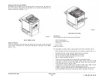
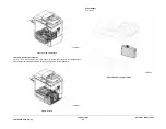
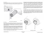
Figure 18
.
Figure 18 Stripper assembly location
The M4 drive motor is run in reverse to lock and unlock the stripper assembly. M4 also pro-
vides drive to the 'J' and 'L' paper path nips (part of the stripper assembly). Unlatching can also
be achieved via a screw at the front of the motor block. Placing the screw slot at approximately
the horizontal position will unlock the stripper assembly. During normal machine operation the
mechanism will automatically move to the unlocked position when a jam occurs.
The stripper cam home sensor sits behind the front stripper cam latch arm. This is an optical
sensor which is blocked by a flag when in the stripper operation position. However, the stripper
assembly can be unlatched and still have the arm in the home position. Since the stripper han-
dle must be in the operational position before the front door is closed, this is not considered an
issue by the PDT but means that the operator cannot be informed they have failed to close the
stripper assembly.
During normal operation, the stripper assembly is locked in position. When the front door is
opened while a jam is present in the stripper area, the stripper cam arm should move to the
home position which allows the stripper assembly to be unlatched. There is a concern that this
may confuse customers and this latch may be broken. Should the stripper fail to home and
unlatch, there is a screw slot accessible through the front motor block frame (to the right and
below the transfix flexure encoder) which will allow the technician to manually turn the M4
motor to home the cams.
The stripper blade is coated with Teflon to reduce the build up of ink. However, debris on the
stripper blade can contribute to damage on the lead edge of the media. Additionally the con-
tamination on the blade may come off the blade when it is brought off contact with the drum
and comes up, striking the media approximately 15 mm from the leading edge. The stripper
blade mechanism is ordinarily locked and does not release until the front door is opened. This
is necessary due to the mass of the stripper transport and blade assembly. If it is necessary to
unlock the stripper assembly with power off, a screw slot within the front drum plates that
allows the drives to be turned to an unlocked position (screw slot will be approximately horizon-
tal). The stripper blade is manufactured with a blunt point to greatly reduce the possibility of
personal injury while handling the stripper blade by service personnel for the purposes of
removal and installation. Care should still be taken when handling the unsaddled stripper blade
assembly.
Exit Module
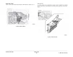
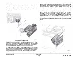
Figure 19
.
Figure 19 Exit module location
Содержание ColorQube 9303 Series
Страница 1: ...Xerox ColorQube 9303 Family Service Manual 708P90290 February 2013...
Страница 4: ...February 2013 ii ColorQube 9303 Family Introduction...
Страница 18: ...February 2013 1 2 ColorQube 9303 Family Service Call Procedures...
Страница 92: ...February 2013 2 68 ColorQube 9303 Family 05F Status Indicator RAPs...
Страница 104: ...February 2013 2 80 ColorQube 9303 Family 12 701 00 65 Status Indicator RAPs...
Страница 200: ...February 2013 2 176 ColorQube 9303 Family 12N 171 Status Indicator RAPs...
Страница 292: ...February 2013 2 268 ColorQube 9303 Family 16D Status Indicator RAPs...
Страница 320: ...February 2013 2 296 ColorQube 9303 Family 42 504 00 42 505 00 Status Indicator RAPs...
Страница 500: ...February 2013 2 476 ColorQube 9303 Family 94B Status Indicator RAPs...
Страница 648: ...February 2013 3 2 ColorQube 9303 Family Image Quality...
Страница 653: ...February 2013 3 7 ColorQube 9303 Family IQ 1 Image Quality Figure 1 IQ defects 1...
Страница 654: ...February 2013 3 8 ColorQube 9303 Family IQ 1 Image Quality Figure 2 IQ defects 2...
Страница 655: ...February 2013 3 9 ColorQube 9303 Family IQ 1 Image Quality Figure 3 IQ defects 3...
Страница 656: ...February 2013 3 10 ColorQube 9303 Family IQ 1 Image Quality Figure 4 IQ defects 4...
Страница 657: ...February 2013 3 11 ColorQube 9303 Family IQ 1 Image Quality Figure 5 IQ defects 5...
Страница 658: ...February 2013 3 12 ColorQube 9303 Family IQ 1 Image Quality Figure 6 IQ defects 6...
Страница 659: ...February 2013 3 13 ColorQube 9303 Family IQ 1 Image Quality Figure 7 IQ defects 7 Figure 8 IQ defects 8...
Страница 660: ...February 2013 3 14 ColorQube 9303 Family IQ 1 Image Quality Figure 9 IQ defects 9...
Страница 661: ...February 2013 3 15 ColorQube 9303 Family IQ 1 Image Quality Figure 10 IQ defects 10...
Страница 662: ...February 2013 3 16 ColorQube 9303 Family IQ 1 Image Quality Figure 11 IQ defects 11...
Страница 663: ...February 2013 3 17 ColorQube 9303 Family IQ 1 Image Quality Figure 12 IQ defects 12...
Страница 664: ...February 2013 3 18 ColorQube 9303 Family IQ 1 Image Quality Figure 13 IQ defects 13...
Страница 707: ...February 2013 3 61 ColorQube 9303 Family IQ 15 Image Quality Figure 4 Corrupt image data Figure 5 Service test pattern...
Страница 728: ...February 2013 3 82 ColorQube 9303 Family IQ 29 IQ 30 Image Quality...
Страница 736: ...February 2013 3 90 ColorQube 9303 Family TP 15 Image Quality Figure 2 Media path test pages...
Страница 752: ...February 2013 3 106 ColorQube 9303 Family TP 26 Image Quality Figure 1 Print head uniformity colour bands test page...
Страница 758: ...February 2013 3 112 ColorQube 9303 Family IQS 7 IQS 8 Image Quality...
Страница 778: ...February 2013 4 20 ColorQube 9303 Family REP 1 9 Repairs Adjustments...
Страница 794: ...February 2013 4 36 ColorQube 9303 Family REP 3 10 Repairs Adjustments...
Страница 1144: ...February 2013 4 386 ColorQube 9303 Family REP 94 1 Repairs Adjustments...
Страница 1176: ...February 2013 4 418 ColorQube 9303 Family ADJ 62 3 ADJ 62 4 Repairs Adjustments...
Страница 1182: ...February 2013 4 424 ColorQube 9303 Family ADJ 75 3 Repairs Adjustments...
Страница 1184: ...February 2013 4 426 ColorQube 9303 Family ADJ 82 1 Repairs Adjustments...
Страница 1186: ...February 2013 4 428 ColorQube 9303 Family ADJ 91 1 Repairs Adjustments...
Страница 1348: ...February 2013 6 56 ColorQube 9303 Family GP 19 General Procedures Information Figure 1 SIM card matrix...
Страница 1378: ...February 2013 6 86 ColorQube 9303 Family GP 29 General Procedures Information Document Handler DADH Figure 4 DADH Sensor Map...
Страница 1380: ...February 2013 6 88 ColorQube 9303 Family GP 29 General Procedures Information High Volume Finisher HVF Figure 6 HVF Sensor Map...
Страница 1552: ...February 2013 6 260 ColorQube 9303 Family dC140 General Procedures Information...
Страница 1576: ...February 2013 6 284 ColorQube 9303 Family dC640 General Procedures Information...
Страница 1578: ...February 2013 6 286 ColorQube 9303 Family dC708 dC715 General Procedures Information...
Страница 1600: ...February 2013 7 2 ColorQube 9303 Family Wiring Data...
Страница 1696: ...February 2013 8 2 ColorQube 9303 Family Principles of Operation...
Страница 1718: ...February 2013 8 24 ColorQube 9303 Family Principles of Operation Figure 1 Sensors in the media path...
Страница 1808: ...February 2013 8 114 ColorQube 9303 Family Principles of Operation...
Страница 1809: ...XEROX EUROPE...
Страница 1810: ...XEROX EUROPE...
Страница 1811: ...XEROX EUROPE...
Страница 1812: ...XEROX EUROPE...

