


February 2013
6-39
ColorQube® 9303 Family
GP 10
General Procedures/Information
GP 10 How to Check a Motor
This procedure describes how to check the following motors:
•
Two Wire DC Motor
.
•
DC Motor with Integral Encoder
•
Four Wire Stepper Motor
•
Six Wire Stepper Motor
.
Initial Actions
WARNING
Switch off the electricity to the machine. Refer to
GP 14
. Disconnect the power cord
from the customer supply while performing tasks that do not need electricity. Electricity
can cause death or injury. Moving parts can cause injury.
1.
Check that the motor is free to rotate.
2.
Check that all the motors mechanisms are clean, free to move and lubricated correctly.
3.
Enter the component control code for the motor, refer to
dC330
. Run the motor for 30 sec-
onds, if the motor shows signs of or can be heard to slow down, then the motor is defec-
tive. Install a new motor.
4.
Perform the appropriate procedure:
•
Two Wire DC Motor
.
•
DC Motor with Integral Encoder
•
Four Wire Stepper Motor
.
•
Six Wire Stepper Motor
.
NOTE: The voltages, PJ numbers, pin numbers and PWB names shown are an example
only. Go to the wiring diagram associated with the RAP for the correct information.
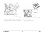
Two Wire DC Motor
NOTE: In cases where the motor may be driven forward or backward, the same two feed wires
are used, but the voltages on them are reversed, to reverse the motor direction. Such motors
may have two component control codes, for forward and reverse. A typical application is a tray
lift motor with a tray-up and a tray-down direction.
•
Go to the wiring diagram shown in
Figure 1
. Disconnect R011. Check that the drive volt-
age, in this case +24V, is measured when the component control code for the motor is
entered. If the drive voltage is measured, install a new motor. If the drive voltage is not
measured, continue to the next step.
•
Disconnect PJ202. Check that the drive voltage can be measured on the PWB when the
component control code for the motor forward is entered. If no drive voltage is measured,
check the power to the PWB. If the power is good install a new PWB. If the drive voltage
is measured at the PWB, check the wiring to the motor. Repair or install new wiring.
References:
•
01H
+24V Distribution RAP.
•
01L
0V Distribution RAP.
•
REP 1.1
Wiring Harness Repairs.
DC Motor with Integral Encoder
NOTE: This type of motor has the normal drive voltages for a DC motor, plus the +5V and 0V
lines for the encoder. The encoder has two outputs, A and B, pro5V pulses when the
motor is on. When the motor is running in one direction, the encoder A pulses lead the encoder
B pulses. In the other direction, encoder B pulses lead encoder A pulses. In this way the con-
troller can detect that the motor is running in the correct direction.
Check the operation of the motor as follows:
•
Go to wiring diagram shown in
Figure 1
. Disconnect PJA. Check that the drive voltage, in
this case +50V, is measured between pins 5 and 7 when the component control code for
the motor is entered. If the drive voltage is present, install a new motor.
•
Disconnect PJ104. Check that the drive voltage is measured between pins 1 and 6, when
the component control code for the motor is entered. If the drive voltage is present, check
the wiring and connectors to the motor. If the drive voltage is not present, check the power
to the media path driver PWB. If the power to the PWB is good, install a new media path
driver PWB.
References:
•
01J
+50V Distribution RAP.
•
01D
+5V Distribution RAP.
•
REP 1.1
Wiring Harness Repairs.
NOTE: When checking for the presence of +5V pulses, use the standard digital multimeter.
Using the DC volts range, or the AC volts range, expect to obtain a reading greater than 1V
and less than 4 volts, while the motor is running. The actual value will depend on the meter’s
reaction to square waves and to the particular frequency of the pulses. It is common to obtain a
reading of 2 to 3 volts. If the meter has a minimum and maximum recording facility, expect a
maximum value of 4.9V, and a minimum value of 0.2V.
Check the operation of the encoder as follows:
•
Go to wiring diagram shown in
Figure 1
. At PJA, check for pulses on pins 2 and 4 to GND
when the motor is running. If pulses are not present, go to the next step on this list. If
pulses are present, check for pulses at PJ104, pins13 and 15 to GND. If pulses are not
present at PJ104, check the wiring to the motor and repair to install new wiring. If pulses
are present at PJ104, install a new media path driver PWB.
•
Pulses are not present at PJA, pins 2 and 4, when the motor is running. Disconnect PJA
and check for +5V between pins 1 and 3. If +5V is measured, install a new motor. If +5V is
not measured, disconnect PJ104. Check for +5V between pins 2 and 14 on the PWB. If
+5V is measured, check the wiring to the motor, and repair or install new wiring. If +5V is
not measured at the PWB, check the power to the PWB. If the power is good, install a
new media path driver PWB.
References:
•
01D
+5V Distribution RAP.
•
01L
0V Distribution RAP.
•
REP 1.1
Wiring Harness Repairs.
Содержание ColorQube 9303 Series
Страница 1: ...Xerox ColorQube 9303 Family Service Manual 708P90290 February 2013...
Страница 4: ...February 2013 ii ColorQube 9303 Family Introduction...
Страница 18: ...February 2013 1 2 ColorQube 9303 Family Service Call Procedures...
Страница 92: ...February 2013 2 68 ColorQube 9303 Family 05F Status Indicator RAPs...
Страница 104: ...February 2013 2 80 ColorQube 9303 Family 12 701 00 65 Status Indicator RAPs...
Страница 200: ...February 2013 2 176 ColorQube 9303 Family 12N 171 Status Indicator RAPs...
Страница 292: ...February 2013 2 268 ColorQube 9303 Family 16D Status Indicator RAPs...
Страница 320: ...February 2013 2 296 ColorQube 9303 Family 42 504 00 42 505 00 Status Indicator RAPs...
Страница 500: ...February 2013 2 476 ColorQube 9303 Family 94B Status Indicator RAPs...
Страница 648: ...February 2013 3 2 ColorQube 9303 Family Image Quality...
Страница 653: ...February 2013 3 7 ColorQube 9303 Family IQ 1 Image Quality Figure 1 IQ defects 1...
Страница 654: ...February 2013 3 8 ColorQube 9303 Family IQ 1 Image Quality Figure 2 IQ defects 2...
Страница 655: ...February 2013 3 9 ColorQube 9303 Family IQ 1 Image Quality Figure 3 IQ defects 3...
Страница 656: ...February 2013 3 10 ColorQube 9303 Family IQ 1 Image Quality Figure 4 IQ defects 4...
Страница 657: ...February 2013 3 11 ColorQube 9303 Family IQ 1 Image Quality Figure 5 IQ defects 5...
Страница 658: ...February 2013 3 12 ColorQube 9303 Family IQ 1 Image Quality Figure 6 IQ defects 6...
Страница 659: ...February 2013 3 13 ColorQube 9303 Family IQ 1 Image Quality Figure 7 IQ defects 7 Figure 8 IQ defects 8...
Страница 660: ...February 2013 3 14 ColorQube 9303 Family IQ 1 Image Quality Figure 9 IQ defects 9...
Страница 661: ...February 2013 3 15 ColorQube 9303 Family IQ 1 Image Quality Figure 10 IQ defects 10...
Страница 662: ...February 2013 3 16 ColorQube 9303 Family IQ 1 Image Quality Figure 11 IQ defects 11...
Страница 663: ...February 2013 3 17 ColorQube 9303 Family IQ 1 Image Quality Figure 12 IQ defects 12...
Страница 664: ...February 2013 3 18 ColorQube 9303 Family IQ 1 Image Quality Figure 13 IQ defects 13...
Страница 707: ...February 2013 3 61 ColorQube 9303 Family IQ 15 Image Quality Figure 4 Corrupt image data Figure 5 Service test pattern...
Страница 728: ...February 2013 3 82 ColorQube 9303 Family IQ 29 IQ 30 Image Quality...
Страница 736: ...February 2013 3 90 ColorQube 9303 Family TP 15 Image Quality Figure 2 Media path test pages...
Страница 752: ...February 2013 3 106 ColorQube 9303 Family TP 26 Image Quality Figure 1 Print head uniformity colour bands test page...
Страница 758: ...February 2013 3 112 ColorQube 9303 Family IQS 7 IQS 8 Image Quality...
Страница 778: ...February 2013 4 20 ColorQube 9303 Family REP 1 9 Repairs Adjustments...
Страница 794: ...February 2013 4 36 ColorQube 9303 Family REP 3 10 Repairs Adjustments...
Страница 1144: ...February 2013 4 386 ColorQube 9303 Family REP 94 1 Repairs Adjustments...
Страница 1176: ...February 2013 4 418 ColorQube 9303 Family ADJ 62 3 ADJ 62 4 Repairs Adjustments...
Страница 1182: ...February 2013 4 424 ColorQube 9303 Family ADJ 75 3 Repairs Adjustments...
Страница 1184: ...February 2013 4 426 ColorQube 9303 Family ADJ 82 1 Repairs Adjustments...
Страница 1186: ...February 2013 4 428 ColorQube 9303 Family ADJ 91 1 Repairs Adjustments...
Страница 1348: ...February 2013 6 56 ColorQube 9303 Family GP 19 General Procedures Information Figure 1 SIM card matrix...
Страница 1378: ...February 2013 6 86 ColorQube 9303 Family GP 29 General Procedures Information Document Handler DADH Figure 4 DADH Sensor Map...
Страница 1380: ...February 2013 6 88 ColorQube 9303 Family GP 29 General Procedures Information High Volume Finisher HVF Figure 6 HVF Sensor Map...
Страница 1552: ...February 2013 6 260 ColorQube 9303 Family dC140 General Procedures Information...
Страница 1576: ...February 2013 6 284 ColorQube 9303 Family dC640 General Procedures Information...
Страница 1578: ...February 2013 6 286 ColorQube 9303 Family dC708 dC715 General Procedures Information...
Страница 1600: ...February 2013 7 2 ColorQube 9303 Family Wiring Data...
Страница 1696: ...February 2013 8 2 ColorQube 9303 Family Principles of Operation...
Страница 1718: ...February 2013 8 24 ColorQube 9303 Family Principles of Operation Figure 1 Sensors in the media path...
Страница 1808: ...February 2013 8 114 ColorQube 9303 Family Principles of Operation...
Страница 1809: ...XEROX EUROPE...
Страница 1810: ...XEROX EUROPE...
Страница 1811: ...XEROX EUROPE...
Страница 1812: ...XEROX EUROPE...


