background image

February 2013

5-44

ColorQube® 9303 Family

PL 12.160

Parts Lists

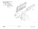
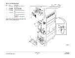
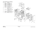
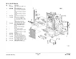
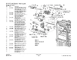
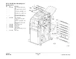
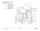
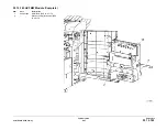
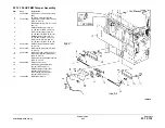
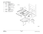
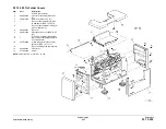
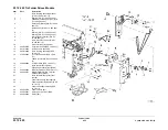
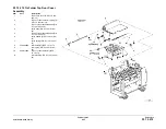
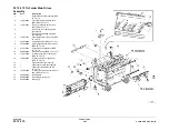
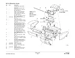
PL 12.160 HVF BM Back Stop Motor

Item

Part

Description

1

Ground wire (P/O PL 12.160 Item 
19)

2

Motor bracket (Not spared)

3

Motor damper (P/O PL 12.160 Item 
19) (REP 12.20-171)

4

BM back stop motor (MOT12-255) 
(P/O PL 12.160 Item 19) (REP 
12.20-171)

5

Pulley (Not spared)

6

BM back stop bearing (Not spared) 
(REP 12.26-171)

7

023E23300

BM back stop drive belt (REP 
12.20-171)

8

809E78370

BM back stop tensioner spring 
(REP 12.20-171)

9

Allen key (3mm) (Not spared)

10

848E40480

Sensor cover

11

BM back stop bearing (Not spared) 
(REP 12.26-171)

12

BM back stop idler bracket (Not 
spared) (REP 12.26-171)

13

BM back stop idler shaft (Not 
spared)

14

BM back stop tensioner link (Not 
spared)

15

809E25100

BM back stop link spring (REP 
12.26-171)

16

012E20870

BM back stop link (REP 12.26-171)

17

LH frame plate (Not spared)

18

107E22600

BM guide home sensor (Q12-204)

19

127K54710

BM back stop motor assembly 
(REP 12.20-171)

Содержание ColorQube 9303 Series

Страница 1: ...Xerox ColorQube 9303 Family Service Manual 708P90290 February 2013...

Страница 2: ...of any inaccuracies or omissions All service documentation is supplied to Xerox external customers for informational purposes only Xerox service documentation is intended for use by certified product...

Страница 3: ...bout This Manual iii How To Use This Manual iv Remote Control Panel iv Change History v Documentation Symbol vii Mod Tag Identification vii Voltages Resistances and Tolerances viii Safety Information...

Страница 4: ...February 2013 ii ColorQube 9303 Family Introduction...

Страница 5: ...nose isolate and repair image quality faults Section 4 Repairs Adjustments This section contains all the repair and adjustment procedures Repairs Repairs include procedures for the removal and install...

Страница 6: ...ion or statement if not strictly observed could result in personal injury A translated version of all warnings is in Translated Warnings CAUTION A caution is used whenever an operation or maintenance...

Страница 7: ...3 Single Board Controller PWB 3 of 3 Wiring Diagram 8 2 Media Path Driver PWB 2 of 5 Wiring Diagram 9 8 Marking Unit Heater PWB Bus Update June 2012 The following procedures are updated 12 024 00 171...

Страница 8: ...12 06 REP 3 8 Hard Disk Drive REP 12 6 171 HVF Ejector Assembly REP 89 2 Registration Preheat Pumps PL 1 15 PL 3 11 PL 5 15 PL 5 35 PL 12 110 PL 20 10 PL 31 11 PL 88 10 PL 88 11 PL 91 20 PL 91 25 GP 1...

Страница 9: ...ge from electrostatic discharge Observe all ESD procedures to avoid component damage Mod Tag Identification Figure 1 shows the Mod Tag identification symbols Figure 1 Mod Tag identification symbols Th...

Страница 10: ...mples of RAP Reference Text Throughout the manual there are linked references that extend the diagnostic procedure or add more information GP 11 How to Check a Sensor NOTE This links to a General Proc...

Страница 11: ...f health and safety incidents involving Xerox products and to ensure Xerox regulatory compliance IV Definitions Incident An event or condition occurring in a customer account that has resulted in inju...

Страница 12: ...r a la extensi n de la contaminaci n y aumen tar a el peligro de deslizamiento WARNING Do not clean the stripper blade The stripper blade is very sharp and can cause injury If the stripper blade is di...

Страница 13: ...the machine while a ground circuit is disconnected Ground circuits ensure that the machine remains safe during a fault condition DANGER Ne pas mettre la machine sous tension si un circuit de mise la m...

Страница 14: ...measuring AC mains line voltage Electricity can cause death or injury DANGER Prendre des pr cautions lors du relev de la tension de la prise de courant alternatif L lectricit peut entra ner des blessu...

Страница 15: ...como desa coplar el apilador grapadora de baja capacidad WARNING Take care not to topple Tray 5 Tray 5 is unstable when undocked from the machine Do not show the customer how to undock Tray 5 DANGER...

Страница 16: ...nicht in abgesenkter Position entfernen Bei abgesenktem Vorlageneinzug sind die Ausgleichsfedern zusammengedr ckt und k nnen bei Fre igabe Verletzungen verursachen AVISO No quite el alimentador de do...

Страница 17: ...013 1 1 ColorQube 9303 Family Service Call Procedures 1 Service Call Procedures SCP 1 Initial Actions 1 3 SCP 2 Call Actions 1 3 SCP 3 Fault Analysis 1 4 SCP 4 Subsystem Maintenance 1 7 SCP 5 Final Ac...

Страница 18: ...February 2013 1 2 ColorQube 9303 Family Service Call Procedures...

Страница 19: ...t easily visible to a customer 5 Check the machine service log book for previous actions that relate to this call 6 Go to SCP 2 Call Actions SCP 2 Call Actions Use SCP 2 Call Actions during a service...

Страница 20: ...n the UI touch screen is illuminated and the machine then powers off The UI touch screen repeatedly cycles back to the install wizard screen If the UI display stops on the splash screen Figure 1 go to...

Страница 21: ...Unload PTU RAP 12J 171 Inserter Paper Sensing and 5V Supply RAP 12K 171 HVF Initialization Failure RAP 12L 171 Tri Folder Not Detected RAP 12N 171 Chad Bin Present and Bin Full RAP 12M 171 Buffer Clam...

Страница 22: ...are Kit Contents GP 25 First Copy Print Out Time and Power On Off Time GP 26 Restriction of Hazardous Substances RoHS GP 27 Cleaning Procedure GP 28 Marking Unit Assembly Wiring Harnesses GP 29 Compon...

Страница 23: ...heets fed from tray 1 after last HFSI reset 600k feeds PL 81 25 Item 6 PL 81 25 Item 9 PL 81 25 Item 11 Tray 2 feed Feed rolls All sheets fed from tray 2 after last HFSI reset 600k feeds PL 81 26 Item...

Страница 24: ...in the Call Closeout window in service mode 7 Operate the machine in all modes 8 Make copies and or prints from all trays and check the registration and copy quality 9 Make a proof copy or print of a...

Страница 25: ...Foreign Device PWB Fault RAP 2 50 Chain 5 DADH 05 250 00 05 251 00 DADH Checksum Error RAP 2 51 05 252 00 DADH Stepper Controller Communications Error 2 51 05 253 00 05 254 00 DADH Communications Err...

Страница 26: ...ct RAP2 137 12 369 00 171 to 12 377 00 171 HVF Stapler Position and Priming RAP 2 139 12 392 00 171 to 12 395 00 171 HVF Front Tamper Fault RAP 2 142 12 396 00 171 to 12 399 00 171 HVF Rear Tamper Fau...

Страница 27: ...213 16 609 07 Unknown Message Received RAP 2 213 16 609 19 16 609 105 Too Many IPC Handlers Invalid RPC Data RAP 2 214 16 609 26 Fault Service Encountered Error RAP 2 214 16 609 46 to 16 609 92 Inval...

Страница 28: ...9 16 758 26 Unable to Write NVM Value RAP 2 246 16 758 35 16 758 46 16 758 47 16 758 66 16 758 67 16 758 93 16 759 09 16 759 14 16 759 19 16 759 26 Service Run Loop Failed RAP 2 247 16 759 46 16 759 4...

Страница 29: ...er Speed Reset Error RAP 2 299 62 476 00 Scan Carriage Home Sensor RAP 2 300 62 477 00 to 62 481 00 Timing Errors RAP 2 301 62 484 00 Apps Code Not Present RAP 2 301 62 485 00 12V Supply Error RAP 2 3...

Страница 30: ...0 91 575 00 Wiper Vertical Error RAP 2 376 91 574 00 91 576 00 91 598 00 Wiper Horizontal Error RAP 2 377 91 586 00 Quad Wave Amplifier Short RAP 2 378 91 587 00 91 588 00 Quad Wave Amplifier Thermal...

Страница 31: ...00 Ink Melt Conductivity Error RAP 2 440 93 549 00 to 93 552 00 and 93 557 00 to 93 560 00 Printheads 1 and 3 Printhead Reservoir Fill Error RAP 2 440 93 553 00 to 93 556 00 and 93 561 00 to 93 564 0...

Страница 32: ...6 00 to 99 640 00 PEST Error 27 RAP 2 502 99 641 00 to 99 655 00 PEST Error 28 RAP 2 503 99 656 00 to 99 670 00 PEST Error 29 RAP 2 504 99 671 00 to 99 685 00 PEST Error 30 RAP 2 505 99 686 00 to 99 7...

Страница 33: ...tch PL 82 10 Item 10 Media path driver PWB PL 1 15 Item 5 PL 1 15 PL 1 15 Item 4 01 505 00 01 506 00 Check that S01 101 is installed correctly 01 506 00 Upper Left Door Open RAP 01 506 00 The upper do...

Страница 34: ...itched off while performing tasks that do not need electricity Refer to GP 14 Disconnect the power cord Electricity can cause death or injury Moving parts can cause injury Switch off the machine then...

Страница 35: ...ed PJ and the chassis The circuit is good Y N Go to 01F and follow the procedure for the IME controller PWB Go to 01F and follow the procedure for the Quad wave amp PWB Refer to WD 1 5 Disconnect PJDC...

Страница 36: ...1 5V Y N Install a new power supply unit PL 1 15 Item 2 Install a new drum driver PWB PL 1 15 Item 4 Perform the RAP s given by the hard PEST fault code s 50V Short Circuit Check Procedure Switch off...

Страница 37: ...being updated Procedure WARNING Ensure that the electricity to the machine is switched off while performing tasks that do not need electricity Refer to GP 14 Disconnect the power cord Electricity can...

Страница 38: ...ch off the machine GP 14 Check pin 27 of PJ902 on the drum driver PWB Pin 27 is short circuit to ground Y N Install a new drum driver PWB PL 1 15 Item 4 Repair the wiring REP 1 1 Either the power supp...

Страница 39: ...after 60 seconds Y N Either the power supply unit is not enabled or is faulty or there is a short circuit on the 50V or 50V output circuits NOTE The voltage on PJ902 at pin 28 must be greater than 2 5...

Страница 40: ...ir and Jetstack Heaters Check Upper Umbilical Heater Check Head 2 Reservoir and Jetstack Heaters Check Head 4 Reservoir and Jetstack Heaters Check Power to the Power Supply Unit Check Procedure Check...

Страница 41: ...heaters Repair the wiring as necessary refer to REP 1 1 As necessary install a new drum PL 94 20 Item 1 Go to Thermal Cutout Check Registration Pre Heaters Check Procedure Switch off the electricity t...

Страница 42: ...isconnect the power cord Refer to WD 9 8 Disconnect PJ701 from the marking unit heater PWB Check the electrical resistance of the lower umbilical heater by measuring the resistance across pin 1 to pin...

Страница 43: ...PJ401 harness as follows Head 2 reservoir heater pin 2 to pin 3 Expect a cold resistance of approximately 95 105 ohms Head 2 first half jetstack heater pin 5 to pin 4 Expect a cold resistance of appro...

Страница 44: ...r the wiring REP 1 1 or install a new PWB or power supply unit PL 1 15 Item 2 as necessary Refer to GP 15 for the location and function of the LED s on the PWB s NOTE Many of the PWB s have distributi...

Страница 45: ...om the IME controller PWB to the quad wave amp PWB refer to WD 9 5 For 3 3V ESTAR faults on the quad wave amplifier PWB refer to WD 9 13 If necessary install a new quad wave amp PWB PL 92 10 Item 3 In...

Страница 46: ...aults on the single board controller PWB refer to WD 3 1 WD 3 2 If necessary repair the wiring REP 1 1 If necessary install a new single board controller PWB PL 3 11 Item 13 Scanner PWB To view the 3...

Страница 47: ...istribution fault go to PWB Checks Perform the RAP s given by the hard PEST fault code s then return to this RAP PWB Checks Check the PWB s below to determine which PWB has the distribution fault Foll...

Страница 48: ...necessary REP 1 1 If necessary install a new power distribution PWB PL 3 11 Item 1 3 Tray Module PWB To view the 5V distribution from the media path driver PWB refer to WD 8 2 For 5V faults on the 3 t...

Страница 49: ...r the wiring as necessary REP 1 1 If necessary install a new LCSS PWB PL 12 75 Item 1 HVF PWB To view the 5V distribution from the HVF power supply module refer to WD 12 6 For 5V faults on the HVF ref...

Страница 50: ...NOTE Many PWB s have distribution fuses PWB Checks IME Controller PWB Marking Unit Driver PWB Solenoid Patch PWB Drum Driver PWB Cleaning Unit Media Path Driver PWB Registration Pre heat Interface PWB...

Страница 51: ...e Power Distribution PWB To view the 12V distribution from the power supply unit refer to WD 1 5 For 12V faults on the power distribution PWB refer to WD 1 6 WD 1 7 Check for 12V on both sides of fuse...

Страница 52: ...good Y N Check for short circuits Refer to the 01 525 00 24V 12V 5V Short Circuit and Over load RAP 12V short circuit check NOTE The 12V supply is protected via a foldback circuit A short circuit wil...

Страница 53: ...s RAP to diagnose 17V supply and distribution faults Procedure WARNING Ensure that the electricity to the machine is switched off while performing tasks that do not need electricity Refer to GP 14 Dis...

Страница 54: ...the 24V 12V 12V and 5V supplies in the power supply unit The voltage is greater than 2 5V Y N Check the condition of the drum driver power supply interface cable between PJDC2 on the power supply unit...

Страница 55: ...PWB Between PJ8 pins 1 3 and 5 on the power distribution PWB and PJ188 pins 1 2 and 3 on the DADH PWB Repair the wiring as necessary REP 1 1 If necessary install a new power distribution PWB PL 3 11 I...

Страница 56: ...ents that follow are driven from 24V from the LCSS PWB Docking interlock switch S12 177 PL 12 15 Item 2 Front door interlock switch S12 303 PL 12 75 Item 5 Transport motor 1 MOT12 223 PL 12 40 Item 2...

Страница 57: ...0 The components that follow are driven from 24V from the tri folder PWB Tri folder top cover interlock switch S12 210 PL 12 215 Item 3 Tri folder front door interlock switch S12 209 PL 12 215 Item 2...

Страница 58: ...unit driver PWB PL 92 10 Item 4 Quad wave amp PWB PL 92 10 Item 3 Repair the wiring as necessary REP 1 1 If necessary install a new IME controller PWB PL 92 10 Item 1 Media Path Driver PWB To view the...

Страница 59: ...sup ply is available in the power supply unit The red LED is lit Y N The red LED is extinguished and the AC supply is good Check the PEST fault history dC123 There are hard PEST faults shown Y N Perf...

Страница 60: ...WB To view the 50V distribution from the IME controller PWB refer to WD 9 5 For 50V faults on quad wave amp PWB refer to WD 9 13 Repair the wiring as necessary REP 1 1 If necessary install a new quad...

Страница 61: ...Power Distribution PWB Single Board Controller PWB UI Control PWB Touch Screen and UI Status PWB Foreign Device Interface PWB DADH PWB Scanner PWB Tray 5 Control PWB 3 Tray Module PWB Media Path Driv...

Страница 62: ...cessary install a new cleaning unit PWB PL 94 10 Item 21 or associated compo nents Printheads 1 2 3 and 4 PWB s Refer to WD 9 20 and WD 9 21 Repair the wiring as necessary REP 1 1 If necessary install...

Страница 63: ...electricity Refer to GP 14 Disconnect the power cord Electricity can cause death or injury Moving parts can cause injury 1 Switch the machine off then switch on the machine GP 14 02 315 00 Service Reg...

Страница 64: ...14 Disconnect the power cord Electricity can cause death or injury Moving parts can cause injury 1 Switch the machine off then switch on the machine GP 14 02 320 00 Data Time Out Error RAP 02 320 00 U...

Страница 65: ...ck the communications cable between PJ905 on the UI PWB and PJ19 on the single board controller PWB If necessary repair the wiring REP 1 1 or install a new user interface harness PL 2 10 Item 7 If nec...

Страница 66: ...ble state after 5 minutes from power up Procedure WARNING Ensure that the electricity to the machine is switched off while performing tasks that do not need electricity Refer to GP 14 Disconnect the p...

Страница 67: ...he wiring between PJ20 on the single board controller PWB and PJ402 on the media path driver PWB Check the wiring between PJ408 on the media path driver PWB and PJ402 on the IME controller PWB Repair...

Страница 68: ...on the machine GP 14 2 Check the network connection to the single board controller PWB PJ14 is correctly inserted 3 Re load the software set GP 4 Machine Software 4 Install new components as necessary...

Страница 69: ...hat do not need electricity Refer to GP 14 Disconnect the power cord Electricity can cause death or injury Moving parts can cause injury Switch off the machine then switch on the machine GP 14 Check t...

Страница 70: ...03 362 00 The single board controller software has failed to exit from a timer loop and has detected that this is caused by an abnormal power condition Initial Actions WARNING Ensure that the electri...

Страница 71: ...cessary Battery PL 3 11 Item 18 NVM module PWB PL 3 11 Item 17 Product enablement key PL 3 11 Item 22 Single board controller PWB PL 3 11 Item 13 7 Perform an NVM restore refer to NVM Save and Restore...

Страница 72: ...has been installed 3 Perform the Initial Actions in 20A Fax Entry RAP 4 Perform the 20G Fax Module Checkout RAP 5 If necessary install a new Fax module PL 20 05 Item 1 6 If necessary re load the soft...

Страница 73: ...electrical noise Go to the OF 10 Intermittent Failure RAP 4 Go to 01A AC Power Distribution RAP and check the power input circuit and its connec tors 03 788 00 CCS Runtime Could Not Enter Power Saver...

Страница 74: ...foreign interface test tool PL 26 10 Item 14 in conjunction with the 7655 65 75 indicator instruction chart To check a foreign interface device if the test tool is not available suitable perform the p...

Страница 75: ...ew DADH PWB PL 5 10 Item 5 05 252 00 DADH Stepper Controller Communications Error 05 252 00 DADH PWB to stepper motors communications have failed Initial Actions WARNING Ensure that the electricity to...

Страница 76: ...nd securely seated Switch on the machine GP 14 2 If the fault was detected during a software upgrade Re load the software set GP 4 Machine Software 3 Refer to WD 3 1 WD 5 2 and WD 6 1 Check the wiring...

Страница 77: ...the position of the machine Remove all documents from the DADH and input tray Make sure that the sensors and the area around the sensors are clean Procedure NOTE The DADH width sensor is a potentiomet...

Страница 78: ...pre reg sensor PL 5 25 Item 1 DADH PWB PL 5 10 Item 5 Completely open the DADH width guides Refer to WD 5 2 Measure the voltage at P J190 pin 8 Completely close the DADH width guides The voltage chan...

Страница 79: ...DH cover Figure 1 If the actuator is damaged install a new DADH top cover PL 5 20 Item 15 Make sure the latch springs PL 5 20 Item 7 are installed correctly Make sure that the top cover closes correct...

Страница 80: ...ons WARNING Ensure that the electricity to the machine is switched off while performing tasks that do not need electricity Refer to GP 14 Disconnect the power cord Electricity can cause death or injur...

Страница 81: ...ADH Make sure that the customer is not using damaged documents If the DADH damages the documents go to the 05E Damaged Documents RAP Clean the DADH feed sensor PL 5 15 Item 2 and the area around the s...

Страница 82: ...udger motor PL 5 15 Item 5 DADH feed assembly PL 5 15 Item 18 DADH PWB PL 5 10 Item 5 Perform the steps that follow Check that the DADH feed sensor Q05 204 is installed correctly Figure 2 If necessary...

Страница 83: ...eck Q05 096 References GP 11 How to Check a Sensor P J186 DADH PWB and P J191 01C 3 3V Distribution PWB 01L 0V Distribution RAP Install new components as necessary DADH TAR sensor PL 5 20 Item 11 DADH...

Страница 84: ...injury Moving parts can cause injury Remove all documents from the DADH Remove the DADH top cover assembly PL 5 20 Item 16 Make sure the harnesses are routed correctly and away from the document path...

Страница 85: ...to the machine is switched off while performing tasks that do not need electricity Refer to GP 14 Disconnect the power cord Electricity can cause death or injury Moving parts can cause injury Remove...

Страница 86: ...ts in duplex mode Exit diagnostics mode Close the DADH top cover Make two copies in duplex mode Check that the second document is held in the feed rolls PL 5 15 Item 1 until the first document is fed...

Страница 87: ...de fault code 05 352 00 Y N Go to the Final Checkout NOTE The exit roll idlers remain lowered for 30 seconds Enter dC330 code 05 100 to check the DADH duplex solenoid SOL05 100 Energize SOL05 100 to l...

Страница 88: ...document in a document set if static electricity is on the input tray If necessary clean the input tray with antistatic fluid refer to ADJ 5 4 Procedure WARNING Ensure that the electricity to the mach...

Страница 89: ...5 099 PL 5 25 Item 9 NOTE When referring to WD 5 1 the Motor on pulses 24V indicated on PJ203 will read 12V on a digital meter References GP 10 How to Check a Motor P J181 DADH PWB and P J203 01H 24V...

Страница 90: ...the DADH top access cover assembly PL 5 20 Item 17 Check the document path for damage Check the takeaway roll idlers and CVT roll idlers PL 5 20 Item 3 for damage Make sure the idlers are clean and ro...

Страница 91: ...3 2 67 ColorQube 9303 Family 05F Status Indicator RAPs 05F Platen Down Failure RAP Use this RAP when the platen down sensor does not respond to opening and closing the DADH Procedure Go to 05 300 00 D...

Страница 92: ...February 2013 2 68 ColorQube 9303 Family 05F Status Indicator RAPs...

Страница 93: ...nsfix stripper blade PL 10 20 Item 14 If the displayed fault code is 10 112 00 check the drum stripper blade assembly PL 10 12 Item 3 for damage or contamination Refer to REP 10 21 Stripper Blade Gate...

Страница 94: ...nents as necessary Nip C release solenoid PL 82 15 Item 4 Media path driver PWB PL 1 15 Item 5 Enter dC330 code 82 008 to energize the nip D release solenoid SOL82 008 PL 70 30 Item 13 SOL82 008 energ...

Страница 95: ...to WD 8 5 Check Q10 017 Refer to GP 11 How to Check a Sensor PJ905 Media path driver PWB 01D 5V Distribution RAP 01L 0V Distribution RAP Install new components as necessary Exit sensor 15 PL 10 15 Ite...

Страница 96: ...ransfix load rear position error 10 523 00 Transfix unload front position error 10 524 00 Transfix unload rear position error 10 525 00 Transfix motor failure 10 530 00 Transfix gap set failure 10 535...

Страница 97: ...ent short If less than 5 ticks check for open or missing code strip Repair the harness as required REP 1 1 The display changes for all encoders Y N Refer to WD 9 1 and WD 9 3 Check and the wiring betw...

Страница 98: ...o not need electricity Refer to GP 14 Disconnect the power cord Electricity can cause death or injury Moving parts can cause injury CAUTION Use care when working near the drum The drum can be damaged...

Страница 99: ...G Ensure that the electricity to the machine is switched off while performing tasks that do not need electricity Refer to GP 14 Disconnect the power cord Electricity can cause death or injury Moving p...

Страница 100: ...RAPs Figure 1 Component location 10 560 00 10 565 00 Transfix Motor Over Current RAP 10 560 00 Front transfix motor over current 10 565 00 Rear transfix motor over current Procedure Refer to the 10 5...

Страница 101: ...ripper blade shaft is installed correctly Slide the shaft forwards and backwards and feel for the shaft to engage on the detent Raise the stripper blade into the operating position Check that the stri...

Страница 102: ...in reverse to latch the stripper gate MOT10 018 runs Y N Refer to WD 8 2 Check MOT10 018 Refer to GP 10 How to Check a Motor P J303 Media Path Driver PWB 01J 50V Distribution RAP 01L 0V Distribution...

Страница 103: ...l a new OCT PL 12 00 Item 1 Procedure 1 Go to WD 12 23 check the OCT wiring 2 Repair the wiring or install a new OCT PL 12 00 Item 1 3 Switch off the machine then switch on the machine GP 14 4 Check t...

Страница 104: ...February 2013 2 80 ColorQube 9303 Family 12 701 00 65 Status Indicator RAPs...

Страница 105: ...gistration in Stapled Sets and Non stapled Sets RAP Check the position of the paddles With the paddle roll in the home position both sets of paddles must be within the output cover if they are not ref...

Страница 106: ...heck Q12 195 Refer to 12G 110 LCSS PWB Damage RAP GP 11 How to Check a Sensor P J307 LCSS PWB 12D 110 LCSS Power Distribution RAP 01L 0V Distribution RAP Install new components as necessary Punch head...

Страница 107: ...xit sensor Q12 106 Initial Actions WARNING Ensure that the electricity to the machine is switched off while performing tasks that do not need electricity Refer to GP 14 Disconnect the power cord Elect...

Страница 108: ...Go to WD 12 4 Check Q12 106 Refer to 12G 110 LCSS PWB Damage RAP GP 11 How to Check a sensor P J313 LCSS PWB 12D 110 LCSS Power Distribution RAP 01L 0V Distribution RAP Install new components as nece...

Страница 109: ...the gap between the entry guide cover PL 12 70 Item 5 and the paper guide PL 12 60 Item 10 If the gap is less than 1mm adjust or install a new entry guide cover Refer to the replace ment procedure in...

Страница 110: ...the AC wall outlet The output device cannot operate without the machine The machine controls the distribution of electricity to the output device for correct power on and power off sequencing Check th...

Страница 111: ...docking interlock S12 177 PL 12 15 Item 2 as follows Check the interlock actuator on the machine is not damaged or missing NOTE The wiring harness passes underneath the docking interlock switch housin...

Страница 112: ...play changes Y N Go to WD 12 1 Check Q12 184 Refer to 12G 110 LCSS PWB Damage RAP GP 11 How to Check a Sensor P J304 LCSS PWB 12D 110 LCSS Power Distribution RAP 01L 0V Distribution RAP Install new co...

Страница 113: ...rs NOTE With reference to WD 12 3 component control codes Code 12 249 increments the stapling unit motor in the forward direction Code 12 045 increments the stapling unit motor in the reverse directio...

Страница 114: ...f the tray settings do not match the paper in the trays Make sure the tray settings are correct Check the condition and the tension of the front tamper drive belt Tensioning is achieved by a spring on...

Страница 115: ...ils to move from the away home position Initial Actions WARNING Ensure that the electricity to the machine is switched off while performing tasks that do not need electricity Refer to GP 14 Disconnect...

Страница 116: ...stall new components as necessary Tamper assembly PL 12 45 Item 1 LCSS PWB PL 12 75 Item 1 Enter dC330 code 12 181 actuate the rear tamper home sensor Q12 181 PL 12 45 Item 3 The display changes Y N G...

Страница 117: ...of paper above bin 1 this has probably been caused by poorly stacked sets failing to actuate the bin 1 upper level sensor Perform the relevant check If paper is overflowing the tray when it is at the...

Страница 118: ...or motor raises the tray until the paper stack height actuates the Bin 1 upper level sensor then the Bin 1 elevator motor lowers the tray to continue the cycle When the tray is emptied the tray return...

Страница 119: ...15 Item 7 is attached to the right hand machine frame and is making the docking interlock Check that the LCSS has initialized correctly refer to 12C 110 LCSS Initialization Failure RAP Procedure Refe...

Страница 120: ...Item 1 Check the wiring between the LCSS PWB and the pause to unload PWB The wiring is good Y N Repair the wiring Install a new pause to unload PWB PL 12 75 Item 3 Enter dC330 code 12 208 to actuate...

Страница 121: ...WB has been determined go to 12G 110 LCSS PWB Damage RAP Check the fuse on the LCSS PWB If the fuse F1 is good continue at the procedure If the fuse not good install a new LCSS PWB PL 12 75 Item 1 Che...

Страница 122: ...ary REP 1 1 Go to WD 12 4 24V is available at PJ315 pin 5 on the LCSS PWB Y N Go to the 12 310 00 110 12 312 00 110 12 313 00 110 Interlocks RAP WARNING Do not install a fuse of a different type or ra...

Страница 123: ...le the LCSS The LCSS is unstable when undocked from the machine Do not show the customer how to undock the LCSS Refer to the 12H 110 Copy Damage in the LCSS RAP Check the following LCSS PWB DIP switch...

Страница 124: ...Damage RAP Use this RAP to determine the cause of damage to the LCSS PWB so that the cause can be repaired before a new LCSS PWB is installed Initial Actions WARNING Ensure that the electricity to the...

Страница 125: ...A9 to A11 20 ohms Staple head unit PL 12 55 Item 5 12M 110 RAP U7 Front tamper motor PJ312 pin A7 to A9 29 ohms PJ312 pin A7 to A10 29 ohms PJ312 pin A8 to A11 29 ohms PJ312 pin A8 to A12 29 ohms Tamp...

Страница 126: ...e machine is switched off while performing tasks that do not need electricity Refer to GP 14 Disconnect the power cord Electricity can cause death or injury Moving parts can cause injury WARNING Take...

Страница 127: ...the output device is not near an air conditioning or ventilation output duct Air flow across the output bins can cause poor stacking 12L 110 Stapling Prime Failure RAP Use this RAP when the staples in...

Страница 128: ...dge and close the door The stapler will now cycle a few times to feed and prime the new sheet of staples Open the door and remove the staple cartridge Examine the sheet of staples that have been fed t...

Страница 129: ...hen switch on the machine GP 14 Check the following The LCSS PWB DIP switch settings refer to 12F 110 LCSS PWB DIP Switch Settings RAP The staple head unit is correctly installed PL 12 55 Item 5 NOTE...

Страница 130: ...eath or injury Moving parts can cause injury Check that the chad bin is fully inserted Check that the actuator for the chad bin level sensor engages in the slot of the chad bin Check that the sensor h...

Страница 131: ...addle roll motor run to check the movement of the paddle Figure 1 The paddle turns Y N Go to WD 12 10 Check the wiring and repair as necessary REP 1 1 Check the paddle roller motor MOT12 238 Refer to...

Страница 132: ...home sensor and stack the code 12 244 for the punch head motor Observe the condition of the sensor on the UI The display changes Y N Go to WD 12 12 Check the wiring from the sensor to the PWB Repair...

Страница 133: ...sen sor PL 12 310 Item 10 to the HVF PWB Check the inserter pickup sensor Refer to GP 11 How to Check a Sensor Install new components as necessary Inserter pickup sensor PL 12 310 Item 10 HVF PWB PL...

Страница 134: ...ched off while performing tasks that do not need electricity Refer to GP 14 Disconnect the power cord Electricity can cause death or injury Moving parts can cause injury Release the crease roll nip pr...

Страница 135: ...or Q12 217 PL 12 185 Item 18 Open and close the staple head carrier The display changes Y N Go to WD 12 16 Check the BM SH carrier closed sensor Q12 217 Refer to GP 11 How to Check a Sensor 12A 171 HV...

Страница 136: ...BM backstop motor to the A4 position Procedure Enter dC330 code 12 204 Actuate the BM guide home sensor Q12 204 PL 12 160 Item 18 The display changes Y N Go to WD 12 18 Check Q12 204 Refer to GP 11 Ho...

Страница 137: ...damaged wiring or bad connectors REP 1 1 If neces sary install new components BM tamper 1 home sensor PL 12 155 Item 1 BM tamper 1 motor PL 12 155 Item 3 BM PWB PL 12 175 Item 10 12 083 00 171 12 440...

Страница 138: ...booklet exit sensor 12 114 00 171 The paper trailing edge is late leaving the HVF booklet exit sensor 12 125 00 171 The entry sensor is not turned on within a specified time 12 190 00 171 The paper l...

Страница 139: ...uns Y N Go to WD 12 17 Check MOT12 251 Refer to GP 10 How to Check a Motor 12A 171 HVF Power Distribution RAP 01L 0V Distribution RAP Install new components as necessary BM compiler motor PL 12 175 It...

Страница 140: ...Power Distribution RAP 01L 0V Distribution RAP Install new components as necessary Entry sensor PL 12 135 Item 2 HVF PWB PL 12 140 Item 2 Enter dC330 code 12 263 to run the bypass feed motor MOT12 26...

Страница 141: ...ll new components as necessary Buffer path sensor PL 12 135 Item 2 HVF PWB PL 12 140 Item 2 Enter dC330 code 12 258 Energize the BM diverter solenoid SOL12 258 PL 12 120 Item 4 The solenoid energizes...

Страница 142: ...ter dC330 code 12 225 Energize the exit diverter solenoid SOL12 225 Figure 1 The solenoid energizes Y N Go to WD 12 8 Check SOL12 225 Refer to GP 12 How to Check a Solenoid or Clutch 12A 171 HVF Power...

Страница 143: ...em 2 Enter dC330 code 12 223 to run the transport motor 1 MOT 12 223 PL 12 120 Item 2 The motor runs Y N Go to WD 12 7 Check the wiring and repair as necessary REP 1 1 Check MOT12 223 Refer to GP 10 H...

Страница 144: ...Refer to GP 11 How to Check a Sensor 12A 171 HVF Power Distribution RAP 01L 0V Distribution RAP Install new components as necessary BM paper present sensor PL 12 185 Item 5 BM PWB PL 12 175 Item 10 G...

Страница 145: ...ray exit sensor Q12 107 PL 12 135 Item 3 The display changes Y N Go to WD 12 7 Check Q12 107 Refer to GP 11 How to Check a Sensor 12A 171 HVF Power Distribution RAP 01L 0V Distribution RAP Install new...

Страница 146: ...m when working in close proximity to the booklet maker while the machine is powered on The crease blade mechanism activates quickly and with great force Turn the crease blade knob 6d to ensure that th...

Страница 147: ...3 BM PWB PL 12 175 Item 10 NOTE The BM crease roll gate motor has two component control codes 12 273 cycles the crease roll gate 12 276 opens the crease roll gate Enter dC330 code 12 273 to cycle the...

Страница 148: ...Indicator RAPs Figure 1 Component location Figure 2 Component location BM crease roll motor encoder Q12 216 BM crease roll motor MOT12 253 BM crease blade motor MOT12 252 BM crease blade motor encode...

Страница 149: ...display changes Y N Go to WD 12 18 Check Q12 213 Refer to GP 11 How to Check a Sensor 12A 171 HVF Power Distribution RAP 01L 0V Distribution RAP Install new components as necessary BM PWB PL 12 175 I...

Страница 150: ...2 126 ColorQube 9303 Family 12 183 00 171 12 184 00 171 Status Indicator RAPs Figure 1 Component location Figure 2 Component location BM entry sensor Q12 089 BM paper present sensor Q12 170 BM exit s...

Страница 151: ...folder for damage Procedure Enter dC330 code 12 165 Manually actuate the tri folder assist gate sensor Q12 165 Figure 1 The display changes Y N Go to WD 12 19 and WD 12 20 Check Q12 165 Refer to GP 1...

Страница 152: ...5 Item 16 BM PWB PL 12 175 Item 10 Enter dC330 code 12 269 to energize the tri folder crease roll clutch CL12 269 Figure 1 The clutch energizes Y N Go to WD 12 19 and WD 12 20 Check CL12 269 Refer to...

Страница 153: ...ry 2013 2 129 ColorQube 9303 Family 12 185 00 171 to 12 187 00 171 Status Indicator RAPs Figure 2 Component location Figure 3 Component location Tri folder exit sensor Q12 166 BM crease roll motor MOT...

Страница 154: ...nents as necessary Inserter pickup sensor PL 12 310 Item 10 Inserter PWB PL 12 310 Item 9 HVF PWB PL 12 140 Item 2 Enter dC330 code 12 084 Manually actuate the inserter TE sensor Q12 084 Figure 1 The...

Страница 155: ...the inserter motor MOT12 261 The motor runs Y N Go to WD 12 14 and WD 12 22 Check MOT12 261 Refer to GP 10 How to Check a Motor 12A 171 HVF Power Distribution RAP 01L 0V Distribution RAP Install new c...

Страница 156: ...Item 2 Enter dC330 code 12 321 Manually actuate the buffer path sensor Q12 321 Figure 1 The display changes Y N Go to WD 12 7 Check Q12 321 Refer to GP 11 How to Check a Sensor 12A 171 HVF Power Dist...

Страница 157: ...be heard Y N Go to WD 12 8 Check MOT12 264 Refer to GP 10 How to Check a Motor 12A 171 HVF Power Distribution RAP 01L 0V Distribution RAP Install new components as necessary Nip split motor PL 12 125...

Страница 158: ...ocking Interlock 12 197 00 171 Top Cover Interlock 12 303 00 171 Front Door Interlock 12 177 00 171 Docking Interlock Check the docking interlock switch S12 177 Figure 1 Check the switch actuator moun...

Страница 159: ...Go to the relevant procedure 12 316 00 171 Inserter Top Cover Interlock 12 319 00 171 Inserter Jam Cover Interlock 12 316 00 171 Inserter Top Cover Interlock Check the inserter top cover interlock sw...

Страница 160: ...20 Check the wiring and repair as neces sary REP 1 1 Check the tri folder top cover interlock switch and the tri folder front door interlock switch S12 209 Refer to GP 13 How to Check a Switch 12A 171...

Страница 161: ...hrough the punch is clear Figure 1 Check the punch module is seated at the rear or the machine Check that a ColorQube punch unit is installed A ColorQube unit has 3 sensors on the unit Figure 1 Proced...

Страница 162: ...dC330 code 12 245 punch unit motor to check that the motor runs The motor runs Y N Go to WD 12 24 Check the wiring and repair as necessary REP 1 1 Check MOT12 245 Refer to GP 10 How to Check a Motor...

Страница 163: ...n be checked they are not spared separately Figure 1 and Figure 2 show the locations of the components Enter dC330 code 12 249 to run the stapler unit 1 motor MOT12 249 and send it to the inboard end...

Страница 164: ...Y N Go to WD 12 10 Check for a change in signal level at PJ301 pin 10 when Q12 317 is being actuated The signal level changes Y N Check the wiring between PJ301 pin 10 and the stapler unit The wiring...

Страница 165: ...Family 12 369 00 171 to 12 377 00 171 Status Indicator RAPs Figure 1 Component location Figure 2 Component location Stapler gate safety switch S12 319 Paper pusher Stapler unit mid home sensor Q12 17...

Страница 166: ...wiring and repair as necessary REP 1 1 Check the front tamper motor home MOT12 226 Refer to GP 10 How to Check a Motor 12A 171 HVF Power Distribution RAP 01L 0V Distribution RAP Install new component...

Страница 167: ...WD 12 14 Check the wiring and repair as necessary REP 1 1 Check the rear tamper motor MOT12 227 Refer to GP 10 How to Check a Motor 12A 171 HVF Power Distribution RAP 01L 0V Distribution RAP Install...

Страница 168: ...sed sensor Q12 217 Figure 1 Open and close the staple head carrier The display changes Y N Go to WD 12 16 Check Q12 217 Refer to GP 11 How to Check a Sensor 12A 171 HVF Power Distribution RAP 01L 0V D...

Страница 169: ...he display changes Y N Go to WD 12 16 Check Q12 222 Refer to GP 11 How to Check a Sensor 12A 171 HVF Power Distribution RAP 01L 0V Distribution RAP Install new components as necessary BM PWB PL 12 175...

Страница 170: ...l HVF BM interlocks must be made to supply 24V to the motors Enter dC330 code 12 271 to check the BM flapper motor MOT12 271 Figure 1 The BM flapper rotates Y N Go to WD 12 19 Check MOT12 271 Refer to...

Страница 171: ...r as necessary REP 1 1 Check the ejector motor MOT12 236 Refer to GP 10 How to Check a Motor 12A 171 HVF Power Distribution RAP 01L 0V Distribution RAP Install new components as necessary Ejector asse...

Страница 172: ...and Figure 3 show the component locations Enter dC330 code 12 242 to lower the bin 1 stacker tray Enter dC330 code 12 249 staple unit 1 forward This moves the ejector module to the out position Enter...

Страница 173: ...e wiring and repair as necessary REP 1 1 Check the ejector lower paddle home sensor S12 099 Refer to GP 13 How to Check a Switch 12A 171 HVF Power Distribution RAP 01L 0V Distribution RAP Install new...

Страница 174: ...51 00 171 to 12 455 00 171 Status Indicator RAPs Figure 2 Component location Figure 3 Component location Ejector lower paddle home sensor S12 099 RIGHT UNDER SIDE VIEW OF EJECTOR Rotate paddle 1 compl...

Страница 175: ...er limit switch Manually actuate the switch Figure 1 The display changes Y N Go to WD 12 13 Check the wiring and repair as necessary REP 1 1 Check S12 190 Refer to GP 13 How to Check a Switch 12A 171...

Страница 176: ...12 322 paper pressing sensor Q12 322 Actuate the paper pressing sensor using a sheet of paper The display changes Y N Go to WD 12 12 Check the wiring and repair as necessary REP 1 1 Check the paper pr...

Страница 177: ...AP and check the AC output voltages Go to WD 12 6 24V is available at PJ111 between pins 1 and 4 Y N Figure 1 24V is available at T001 on the HVF power supply between pins 1 and 5 Y N Install a new HV...

Страница 178: ...F BM interlocks must be made to supply 24V to the motors Enter dC330 code 12 239 to run the paddle unit motor MOT12 239 Figure 1 The motor runs Y N Go to WD 12 10 Check the paddle unit motor MOT12 239...

Страница 179: ...not need electricity Refer to GP 14 Disconnect the power cord Electricity can cause death or injury Moving parts can cause injury NOTE When manually extending the fingers to check the sensors the pre...

Страница 180: ...ly PL 12 110 Item 29 HVF PWB PL 12 140 Item 2 Make several small sets of prints Check that the support fingers extend between each set The support fingers extended Y N Remove the HVF top cover and rea...

Страница 181: ...length sensor 1 Q12 079 Refer to GP 11 How to Check a Sensor 12A 171 HVF Power Distribution RAP 01L 0V Distribution RAP Install new components as necessary Inserter paper length sensor 1 PL 12 300 It...

Страница 182: ...or PL 12 310 Item 11 Inserter PWB PL 12 310 Item 9 HVF PWB PL 12 140 Item 2 Enter the dC330 code 12 260 to energize the inserter clutch CL12 260 The inserter clutch energizes Y N Go to WD 12 14 WD 12...

Страница 183: ...er communications cable PL 12 140 Item 7 Power cord PL 12 140 Item 4 12 762 00 171 12 764 00 171 12 765 00 171 IME To Finisher Communication Failure RAP 12 762 00 171 Communications failure between th...

Страница 184: ...harness end of PJ113 between pins 1 and 2 Y N Check the connectors and harness between T001 and PJ113 Repair the har ness as necessary REP 1 1 Install a new HVF PWB PL 12 140 Item 2 Go to WD 12 6 24V...

Страница 185: ...t used LED 6 red Not used LED 7 red Not used LED 8 red steady This indicates that the HVF top cover front door and docking inter locks are all closed and 24V is available at the HVF module LED 9 red s...

Страница 186: ...mmunications between the booklet maker and the HVF PWB For communications between the HVF PWB and the machine go to WD 12 9 The pulses on the connections between PJ133 and PJ562 cannot be measured but...

Страница 187: ...1 1 Go to WD 12 18 Check Q12 206 Refer to GP 11 How to Check a Sensor 12A 171 HVF Power Distribution RAP 01L 0V Distribution RAP Install new components as necessary BM PWB PL 12 175 Item 10 BM bin 2 9...

Страница 188: ...given in Table 1 Check the machine and HVF BM paper paths for any obstruction that could cause mis alignment of the paper fed to the BM compiling area Procedure Produce three 4 sheet 16 page booklets...

Страница 189: ...s it onto a flat surface Measure the mis alignment of the open side edges of the booklet Figure 2 Open side edge alignment If the open side edge alignment does not conform to the specification in Tabl...

Страница 190: ...ooklet at the centre page and press it onto a flat surface Measure the position of the booklet crease Figure 4 Booklet crease position Table 4 Skew tolerance Paper weight Paper size A4 8 5x11in 8 5x13...

Страница 191: ...ication in Figure 5 perform ADJ 12 8 171 Booklet Staple Position The Booklet is Not Sufficiently Creased Figure 6 Measure the open dimension of the booklets Figure 6 Booklet creasing If the open dimen...

Страница 192: ...k the posi tion of the jam clearance guides 5a 5b and 5C Check the vertical transport rolls and bearings for contamination If necessary remove and clean the drive shaft and the bear ings If the proble...

Страница 193: ...ly for the paper size and that the trays are fully closed Labels must not be fed to bin1 but to bin 0 only It is recommended that transparencies are fed to bin 0 whenever possible Check that the bin 1...

Страница 194: ...1 How to Check a Sensor PJ8 and PJ4 on the Inserter PWB 12A 171 HVF Power Distribution RAP 01L 0V Distribution RAP Install new components as necessary Inserter paper width sensor 1 PL 12 300 Item 13 I...

Страница 195: ...tus Indicator RAPs Figure 1 Component location Figure 2 Component location Inserter unit empty sensor Q12 082 Inserter Pickup sensor Q12 315 Inserter acceleration sensor Q12 316 Inserter paper width s...

Страница 196: ...rocedure If the initialization sequence fails to place any unit at the home position refer to the appropriate RAPs Front tamper not at home refer to 12 392 00 171 to 12 395 00 171 HVF Front tamper Tra...

Страница 197: ...V at PJ563 pin 7 Refer to 12A 171 HVF Power Distribution RAP 01L 0V Distribution RAP 12M 171 Buffer Path Clamp Problems RAP Use this RAP when having problems with the buffer path clamp on the HVF Prob...

Страница 198: ...in present sensor Q12 118 Remove the chad bin and actu ate the sensor manually The display changes Y N Go to WD 12 12 and check the wiring Repair as necessary REP 1 1 Check the chad bin present sensor...

Страница 199: ...February 2013 2 175 ColorQube 9303 Family 12N 171 Status Indicator RAPs Figure 1 Component location Chad bin level sensor Q12 193 Chad bin present sensor Q12 118 UNDERSIDE VIEW...

Страница 200: ...February 2013 2 176 ColorQube 9303 Family 12N 171 Status Indicator RAPs...

Страница 201: ...ury 1 If a single occurrence the network controller ESS will automatically re boot 2 For multiple occurrences reinstall software GP 4 16 001 09 to 16 001 90 Unable to Synchronize Startup RAP 16 001 09...

Страница 202: ...jury Moving parts can cause injury 1 If a single occurrence take no action 2 For multiple occurrences switch off the machine then switch on the machine GP 14 3 If the fault remains reinstall software...

Страница 203: ...on failed 16 005 92 RPC call failure to ESS registration service to register with Procedure WARNING Ensure that the electricity to the machine is switched off while performing tasks that do not need e...

Страница 204: ...njury Moving parts can cause injury 1 If a single occurrence take no action 2 For multiple occurrences switch off the machine then switch on the machine GP 14 3 If the fault remains reinstall software...

Страница 205: ...oving parts can cause injury 1 If a single occurrence switch off the machine then switch on the machine GP 14 2 For multiple occurrences reinstall the software GP 4 16 016 14 16 016 19 Data Store Init...

Страница 206: ...Electricity can cause death or injury Moving parts can cause injury 1 If a single occurrence take no action 2 For multiple occurrences switch off the machine then switch on the machine GP 14 3 If the...

Страница 207: ...es switch off the machine then switch on the machine GP 14 3 If the fault remains reinstall software GP 4 16 026 09 to 16 026 92 Memory Allocation Error RAP 16 026 09 Memory allocation failure 16 026...

Страница 208: ...ngle occurrence take no action 2 For multiple occurrences reinstall the software GP 4 16 028 09 16 028 90 Unable to Complete RPC Call Invalid Range RAP 16 028 09 Unable to complete RPC call 16 028 90...

Страница 209: ...ake no action 2 For multiple occurrences switch off the machine then switch on the machine GP 14 3 If the fault remains reinstall software GP 4 16 031 09 Invalid Event Notification RAP 16 031 09 Inval...

Страница 210: ...ord Electricity can cause death or injury Moving parts can cause injury 1 If a single occurrence take no action 2 For multiple occurrences reinstall the software GP 4 16 040 92 Semaphore Fault RAP 16...

Страница 211: ...e no action 2 For multiple occurrences switch off the machine then switch on the machine GP 14 3 If the fault remains reinstall software GP 4 16 048 14 16 048 90 Cannot Set ESS Client Binding RAP 16 0...

Страница 212: ...ry 1 If a single occurrence take no action 2 For multiple occurrences switch off the machine then switch on the machine GP 14 3 If the fault remains reinstall software GP 4 16 150 09 Cannot Send Regis...

Страница 213: ...If a single occurrence take no action 2 For multiple occurrences switch off the machine then switch on the machine GP 14 3 If the fault remains reinstall software GP 4 16 150 19 Unable to Sync Peer RA...

Страница 214: ...injury 1 Switch off the machine then switch on the machine GP 14 2 If the fault remains reinstall software GP 4 16 150 90 Invalid IPC Request Destination RAP 16 150 90 Invalid IPC request destination...

Страница 215: ...ch on the machine GP 14 2 If the fault remains reinstall software GP 4 16 151 09 to 16 151 19 Invalid IPC Command SNMP Reg Failure RAP 16 151 09 Invalid IPC command 16 151 14 SNMP event registration f...

Страница 216: ...ause death or injury Moving parts can cause injury 1 Switch off the machine then switch on the machine GP 14 2 If the fault remains reinstall software GP 4 16 151 90 Environment Variable Failure RAP 1...

Страница 217: ...2 For multiple occurrences switch off the machine then switch on the machine GP 14 3 If the fault remains reinstall software GP 4 16 152 14 Empty Internal Event Failure RAP 16 152 14 Empty internal ev...

Страница 218: ...e no action 2 For multiple occurrences switch off the machine then switch on the machine GP 14 3 If the fault remains reinstall software GP 4 16 152 26 Unable to Send Request to SESS RAP 16 152 26 Una...

Страница 219: ...ion 2 For multiple occurrences switch off the machine then switch on the machine GP 14 3 If the fault remains reinstall software GP 4 16 153 14 Unable to Initialize Event List RAP 16 153 14 Can not in...

Страница 220: ...jury 1 If a single occurrence take no action 2 For multiple occurrences reinstall software GP 4 16 154 09 ESS Registration Configuration Error RAP 16 154 09 ESS Registration service configuration erro...

Страница 221: ...ty can cause death or injury Moving parts can cause injury 1 Switch off the machine then switch on the machine GP 14 2 If the fault remains reinstall software GP 4 16 154 19 NVM Read Failure RAP 16 15...

Страница 222: ...ause death or injury Moving parts can cause injury 1 If a single occurrence take no action 2 For multiple occurrences reinstall software GP 4 16 156 19 Service Run Loop Failed RAP 16 156 19 Service ru...

Страница 223: ...take no action 2 For multiple occurrences switch off the machine then switch on the machine GP 14 3 If the fault remains reinstall software GP 4 16 161 09 16 164 09 Cannot Send Reg Event List Access...

Страница 224: ...city can cause death or injury Moving parts can cause injury 1 Switch off the machine then switch on the machine GP 14 2 If the fault remains reinstall software GP 4 16 429 00 16 431 00 Unable to Writ...

Страница 225: ...an cause injury 1 Switch off the machine then switch on the machine GP 14 2 If the fault remains reinstall software GP 4 16 433 00 RPC Call Failed RAP 16 433 00 RPC call failed Procedure WARNING Ensur...

Страница 226: ...remains reinstall software GP 4 16 600 07 to 16 600 67 Cannot Create RPC Connection RAP 16 600 07 Cannot create RPC connection to ENS 16 600 35 Cannot create RPC connection to ENS 16 600 46 Cannot cre...

Страница 227: ...lectricity can cause death or injury Moving parts can cause injury 1 If a single occurrence take no action 2 For multiple occurrences switch off the machine then switch on the machine GP 14 3 If the f...

Страница 228: ...can cause death or injury Moving parts can cause injury 1 If a single occurrence switch off the machine then switch on the machine GP 14 2 For multiple occurrences reinstall software GP 4 16 601 68 U...

Страница 229: ...vice registration failure 16 602 09 Unable to unregistered as RPC service during shutdown 16 602 11 RPC server register failed 16 602 28 RPC server registration failed 16 602 35 RPC server registratio...

Страница 230: ...single occurrence switch off the machine then switch on the machine GP 14 2 For multiple occurrences reinstall software GP 4 16 603 46 to 16 603 67 Too Many IPC Handlers RAP 16 603 46 Too many IPC ha...

Страница 231: ...currence switch off the machine then switch on the machine GP 14 2 For multiple occurrences reinstall software GP 4 16 603 105 16 604 14 RPC Call Failure to NC Reg Service RAP 16 603 105 RPC call fail...

Страница 232: ...ry Moving parts can cause injury 1 Switch off the machine then switch on the machine GP 14 2 If the fault remains reinstall software GP 4 16 605 14 16 605 105 Unable to Unregister As RPC Service RPC C...

Страница 233: ...remains reinstall software GP 4 16 605 35 to 16 605 67 RPC Call Failure to ESS RAP 16 605 35 RPC call failure to ESS registration service 16 605 47 RPC call failure to ESS registration service to reg...

Страница 234: ...1 Switch off the machine then switch on the machine GP 14 2 If the fault remains reinstall software GP 4 16 606 35 to 16 606 99 Cannot Register For Events RAP 16 606 35 Cannot register for events 16 6...

Страница 235: ...C Data Unable to Free Resources RAP 16 607 19 Invalid RPC data received 16 607 46 Invalid RPC data received 16 607 47 Invalid RPC disk diagnostic data received 16 607 92 Invalid RPC data received 16 6...

Страница 236: ...f problem persists install a new HDD PL 3 11 Item 2 16 608 28 to 16 608 67 Unable to Free IPC Resources RAP 16 608 28 IPC unregister fail 16 608 35 Unable to free IPC resources 16 608 38 Unable to unr...

Страница 237: ...urrence take no action 2 For multiple occurrences switch off the machine then switch on the machine GP 14 3 If the fault remains reinstall software GP 4 16 609 07 Unknown Message Received RAP 16 609 0...

Страница 238: ...occurrence take no action 2 For multiple occurrences switch off the machine then switch on the machine GP 14 3 If the fault remains reinstall software GP 4 16 609 26 Fault Service Encountered Error R...

Страница 239: ...If a single occurrence take no action 2 For multiple occurrences switch off the machine then switch on the machine GP 14 3 If the fault remains reinstall software GP 4 16 610 00 16 610 07 IPC Send Fa...

Страница 240: ...tware GP 4 16 610 11 to 16 610 90 Unable to Send IPC Message RAP 16 610 11 IPC communication failed 16 610 19 Unable to send IPC message 16 610 26 Unable to send IPC message 16 610 28 IPC communicatio...

Страница 241: ...injury 1 Switch off the machine then switch on the machine GP 14 2 If the fault remains reinstall software GP 4 16 610 99 Unable to Send IPC Message RAP 16 610 99 Unable to send IPC message Procedure...

Страница 242: ...GP 14 3 If the fault remains reinstall software GP 4 16 611 19 to 16 611 47 Unable to Remove RPC Connection RAP 16 611 09 Unable to remove RPC connection 16 611 14 Unable to remove RPC connection 16...

Страница 243: ...ine then switch on the machine GP 14 3 If the fault remains reinstall software GP 4 16 612 09 to 16 612 68 Unable to Do Shutdown Sync RAP 16 612 09 Unable to do shutdown synchronization 16 612 14 Unab...

Страница 244: ...is switched off while performing tasks that do not need electricity Refer to GP 14 Disconnect the power cord Electricity can cause death or injury Moving parts can cause injury 1 Switch off the machin...

Страница 245: ...r cord Electricity can cause death or injury Moving parts can cause injury 1 If a single occurrence switch off the machine then switch on the machine GP 14 2 For multiple occurrences reinstall softwar...

Страница 246: ...616 46 SESS Data Store Environmental Variable RAP 16 615 67 SESS data store environmental variable not set 16 615 90 Corrupt environment variable configuration script error 16 616 35 SESS Faults 206...

Страница 247: ...le occurrences switch off the machine then switch on the machine GP 14 3 If the fault remains reinstall the software GP 4 16 616 67 Submission Of E mail OR IFax Job Failed RAP 16 616 67 Submission of...

Страница 248: ...injury Moving parts can cause injury 1 For a single occurrence switch off the machine then switch on the machine GP 14 2 For multiple occurrences reinstall software GP 4 16 617 47 TAR Extraction Failu...

Страница 249: ...n service failed to respond in time 16 619 26 Could not register with Registration Service Communication failure software error 16 619 46 Unable to unregister with Network Controller Registration Serv...

Страница 250: ...rts can cause injury 1 For a single occurrence switch off the machine then switch on the machine GP 14 2 For a multiple occurrence reinstall software GP 4 16 620 92 16 620 93 16 620 99 Unable to Regis...

Страница 251: ...ing tasks that do not need electricity Refer to GP 14 Disconnect the power cord Electricity can cause death or injury Moving parts can cause injury 1 For single occurrence switch on the machine then s...

Страница 252: ...eath or injury Moving parts can cause injury 1 For a single occurrence switch off the machine then switch on the machine GP 14 2 For multiple occurrences reinstall software GP 4 16 623 35 16 623 47 16...

Страница 253: ...rrences reinstall software GP 4 16 626 00 16 626 11 16 626 38 16 626 47 16 626 67 Memory Leak RAP 16 626 00 Memory leak software bug memory corrupt Virtual memory exhausted Process size exceeding syst...

Страница 254: ...h on the machine GP 14 2 For multiple occurrences reinstall software GP 4 16 628 09 16 629 11 16 629 26 16 629 46 16 629 67 16 629 68 16 629 92 16 629 93 No Acknowledgment For RPC Message RAP 16 628 0...

Страница 255: ...GP 14 2 For multiple occurrences reinstall software GP 4 16 631 19 16 631 46 16 631 19 16 633 19 16 634 46 16 635 07 16 635 35 16 635 46 16 635 99 16 636 35 16 636 99 XDR Data Error RAP 16 631 19 Soft...

Страница 256: ...install software GP 4 16 638 66 16 638 67 16 639 38 16 639 46 16 640 28 16 640 35 16 640 46 16 641 00 16 641 26 16 641 46 O S Failure RAP 16 638 66 Unable to initialize with queue library 16 638 67 Un...

Страница 257: ...644 46 16 644 47 16 644 66 16 644 67 16 645 11 16 645 26 16 645 46 16 645 47 16 645 66 16 645 67 Unable To Read From File RAP 16 644 11 Common logging utility failed to get log size 16 644 26 Common...

Страница 258: ...652 38 16 652 99 16 653 38 16 654 38 16 654 99 16 655 38 16 656 38 Register Failure RAP 16 651 19 IPC OS SESS or SC operation 16 651 35 IPC and OS failure SESS not responding 16 651 99 IPC and OS fai...

Страница 259: ...le occurrence switch off the machine then switch on the machine GP 14 2 For multiple occurrences reinstall software GP 4 16 662 11 16 662 28 16 662 93 16 662 95 16 663 28 16 663 93 16 663 95 Parser Ut...

Страница 260: ...ty can cause death or injury Moving parts can cause injury 1 For a single occurrence switch off the machine then switch on the machine GP 14 2 For multiple occurrences reinstall software GP 4 16 666 1...

Страница 261: ...can cause death or injury Moving parts can cause injury 1 For a single occurrence switch off the machine then switch on the machine GP 14 2 For multiple occurrences reinstall software GP 4 16 668 93 1...

Страница 262: ...ing parts can cause injury 1 For a single occurrence switch off the machine then switch on the machine GP 14 2 For multiple occurrences reinstall software GP 4 16 670 11 16 670 28 16 670 47 16 670 93...

Страница 263: ...tall software GP 4 16 674 09 16 675 00 16 700 00 16 701 00 16 701 99 16 702 00 16 702 95 16 707 00 16 709 00 XSA Database Failure RAP 16 674 09 RPC server not responding 16 675 00 Database server not...

Страница 264: ...isk 16 750 07 Message received from DM not processed correctly 16 750 09 Service tried to register and service is already registered 16 750 11 Template cache file is missing Procedure WARNING Ensure t...

Страница 265: ...currence switch off the machine then switch on the machine GP 14 2 For multiple occurrences reinstall software GP 4 16 750 92 16 750 93 16 750 95 16 751 00 16 751 07 16 751 09 16 751 11 16 751 14 16 7...

Страница 266: ...WARNING Ensure that the electricity to the machine is switched off while performing tasks that do not need electricity Refer to GP 14 Disconnect the power cord Electricity can cause death or injury M...

Страница 267: ...the machine GP 14 2 For multiple occurrences reinstall software GP 4 16 752 66 16 752 67 16 752 92 16 752 93 16 752 95 16 753 09 16 753 14 16 753 19 16 753 26 16 753 28 Scan to FAX Registration Error...

Страница 268: ...njury 1 For a single occurrence switch off the machine then switch on the machine GP 14 2 For multiple occurrences reinstall software GP 4 16 754 14 16 754 19 16 754 26 16 754 28 16 754 35 16 754 46 1...

Страница 269: ...a single occurrence switch off the machine then switch on the machine GP 14 2 For multiple occurrences reinstall software GP 4 16 755 35 16 755 46 16 755 47 16 755 67 16 755 90 16 755 93 16 755 99 16...

Страница 270: ...urrence switch off the machine then switch on the machine GP 14 2 For multiple occurrences reinstall software GP 4 16 757 35 16 757 46 16 757 47 16 757 66 16 757 67 16 757 93 16 758 09 16 758 14 16 75...

Страница 271: ...ower cord Electricity can cause death or injury Moving parts can cause injury 1 For a single occurrence switch off the machine then switch on the machine GP 14 2 For multiple occurrences reinstall sof...

Страница 272: ...16 761 95 Unable to read template pool configuration information 16 762 09 Netware process failed Software error Check fault log for more specific reasons 16 762 14 Invalid internal table type 16 762...

Страница 273: ...69 95 Cannot determine appropriate lock name and address Procedure WARNING Ensure that the electricity to the machine is switched off while performing tasks that do not need electricity Refer to GP 14...

Страница 274: ...machine GP 14 2 For multiple occurrences reinstall software GP 4 16 780 00 to 16 789 47 Other Network Faults 3 RAP 16 780 00 Power save request time out 16 780 09 Software error Check fault log for mo...

Страница 275: ...n load failure software 16 790 47 SESS diagnostic failure 16 791 09 Software error Check fault log for more specific reasons 16 791 19 Scan to file DLM is not defined 16 791 46 DHCP V6 failure 16 791...

Страница 276: ...Web service edge client process death 16 804 47 SESS diagnostic failure 16 805 09 Web service edge client process death 16 805 19 Accounting install failed 16 805 47 SESS diagnostic failure 16 806 00...

Страница 277: ...8 47 SESS diagnostic failure 16 819 47 SESS diagnostic failure Procedure WARNING Ensure that the electricity to the machine is switched off while performing tasks that do not need electricity Refer to...

Страница 278: ...eath or injury Moving parts can cause injury 1 For a single occurrence switch off the machine then switch on the machine GP 14 2 For multiple occurrences reinstall software GP 4 16 840 47 to 16 849 47...

Страница 279: ...ury 1 For a single occurrence switch off the machine then switch on the machine GP 14 2 For multiple occurrences reinstall software GP 4 16 860 47 to 16 869 47 Other Network Faults 11 RAP 16 860 47 No...

Страница 280: ...jury 1 For a single occurrence switch off the machine then switch on the machine GP 14 2 For multiple occurrences reinstall software GP 4 16 880 47 to 16 890 47 Other Network Faults 13 RAP 16 880 47 S...

Страница 281: ...rences reinstall software GP 4 16 900 19 to 16 909 19 Other Network Faults 14 RAP 16 900 19 Failed to open SMC driver 16 901 19 Failed to make ioctl call using SMC driver 16 902 19 Address specified i...

Страница 282: ...jury 1 For a single occurrence switch off the machine then switch on the machine GP 14 2 For multiple occurrences reinstall software GP 4 16 920 19 to 16 929 19 Other Network Faults 16 RAP 16 920 19 E...

Страница 283: ...For multiple occurrences reinstall software GP 4 16 940 19 to 16 949 19 Other Network Faults 18 RAP 16 940 19 Auto upgrade failed Machine in diagnostics mode 16 941 19 Auto upgrade failed Network con...

Страница 284: ...icity Refer to GP 14 Disconnect the power cord Electricity can cause death or injury Moving parts can cause injury 1 For a single occurrence switch off the machine then switch on the machine GP 14 2 F...

Страница 285: ...M 16 981 00 Object handler corrupted Null handle returned Data store corrupt 16 981 35 Unable to obtain job handle which is used to fetch data store attributes 16 982 00 Unknown finishing value return...

Страница 286: ...oving parts can cause injury 1 If a single occurrence switch off the machine then switch on the machine GP 14 2 For multiple occurrences reinstall software GP 4 16 987 19 16 988 19 Server Fax Applicat...

Страница 287: ...Unable to build SESS job identifier for promote routine that converts the job ID returned Null memory allocation error 16 993 00 Unable to get admin name from data store for promote Request library c...

Страница 288: ...template and one other template The fault is present on both templates Y N The template that failed is incorrectly configured Ask the customer or system administra tor to verify the settings of the we...

Страница 289: ...charge Retry the job The job was successful Y N Escalate the fault to the system Administrator If the customer does not have a System Administrator they should contact the Customer Support Centre or...

Страница 290: ...ts that the machine has logged onto the scan server but cannot create a folder inside of the scan directory The creation of the scan folder is neces sary for the machine to successfully complete the c...

Страница 291: ...ing i Select Network Settings ii Select Network Connectivity iii Select Wireless iv Select OK v Select Enable Wireless Network c Check the network name listed next to SSID on the configuration report...

Страница 292: ...February 2013 2 268 ColorQube 9303 Family 16D Status Indicator RAPs...

Страница 293: ...necessary install a new cable PL 3 11 Item 3 Refer to WD 1 5 and WD 3 3 Check the power harness from PJDC4 on the power supply unit to PJ211 on the hard disk drive The wiring is good Y N Repair the h...

Страница 294: ...h or injury Moving parts can cause injury No service action is required Re scan the job 19 409 00 Job Integrity Failure RAP 19 409 00 Video determines that it cannot guarantee the integrity of the job...

Страница 295: ...detected a DMA master abort 19 410 12 The system has detected a Huffman error image encoding error 19 410 13 The system has detected an EOR error Procedure WARNING Ensure that the electricity to the...

Страница 296: ...use injury Switch off the machine then switch on the machine GP 14 Re run the job 19 754 00 Image Disk Change RAP 19 754 00 The system detects that the Image disk configuration present vs not present...

Страница 297: ...rm the routine All Data The fault is cleared Y N Reload the software GP 4 The fault is cleared Y N Go to RAP 20G Fax Module Checkout Go to SCP 5 and complete the final actions Go to SCP 5 and complete...

Страница 298: ...aliza tion Perform the routine All data The fault is cleared Y N Reload the software GP 4 Go to SCP 5 and complete the final actions 20 322 00 Non Volatile Device not Installed RAP 20 322 00 The non v...

Страница 299: ...ommunication Error at power up or reboot 20 339 00 Internal fax card fault 20 341 00 Miscellaneous basic card problems 20 345 00 Fax port 1 modem failure Initial Actions WARNING Ensure that the electr...

Страница 300: ...1 Item 16 The phone line connec tion is good Y N The telephone line has a fault advise the customer to have the line checked by the tele phone company Install new parts in the following order Telephon...

Страница 301: ...NG Ensure that the electricity to the machine is switched off while performing tasks that do not need electricity Refer to GP 14 Disconnect the power cord Electricity can cause death or injury Moving...

Страница 302: ...al Actions WARNING Ensure that the electricity to the machine is switched off while performing tasks that do not need electricity Refer to GP 14 Disconnect the power cord Electricity can cause death o...

Страница 303: ...ded Fax Setting Print Fax Reports Print a Pro tocol Report and check for errors Re enter the details from the fax options 20C Unable To Send A Fax To Some Machines RAP Use this RAP to isolate componen...

Страница 304: ...ivity Report Check for receive calls on the Activity Report Machine probably does not bleep to indicate incoming call Check that the NVM values at NVM ID 200 203 NVM ID 200 423 and 200 426 are set to...

Страница 305: ...tasks that do not need electricity Refer to GP 14 Disconnect the power cord Electricity can cause death or injury Moving parts can cause injury Switch off the machine then switch on the machine GP 14...

Страница 306: ...Fax Problems on Digital Networks RAP Use this RAP to isolate the problem when using digital networks The Fax option was designed as an analogue Group 3 device This will have the best perfor mance when...

Страница 307: ...hile performing tasks that do not need electricity Refer to GP 14 Disconnect the power cord Electricity can cause death or injury Moving parts can cause injury Switch off the machine then switch on th...

Страница 308: ...the machine then switch on the machine GP 14 22 319 04 IOT Integrity Problem While Printing a Job RAP 22 319 04 Integrity problem while printing a job The IOT cycles down and up 10 times without print...

Страница 309: ...death or injury Moving parts can cause injury Switch off the machine then switch on the machine GP 14 22 321 04 Proposal Response Time Out Error RAP 22 321 04 Proposal response time out error RS422 c...

Страница 310: ...e power cord Electricity can cause death or injury Moving parts can cause injury Switch off the machine then switch on the machine GP 14 22 328 00 Incomplete System Information RAP 22 328 00 Incomplet...

Страница 311: ...t the power cord Electricity can cause death or injury Moving parts can cause injury Perform the following 1 Switch off the machine then switch on the machine GP 14 2 Obtain a new PIN and try again 22...

Страница 312: ...the power cord Electricity can cause death or injury Moving parts can cause injury Switch off the machine then switch on the machine GP 14 22 330 03 List Jobs Request Timed Out Between Copy Controller...

Страница 313: ...isconnect the power cord Electricity can cause death or injury Moving parts can cause injury Switch off the machine then switch on the machine GP 14 22 330 05 List Jobs Request Timed Out Between Queue...

Страница 314: ...ath or injury Moving parts can cause injury Switch off the machine then switch on the machine GP 14 22 350 01 22 350 02 Software Detects Non Valid Xerox SOK RAP 22 350 01 Software detected non valid X...

Страница 315: ...appropriate RAP Procedure 1 Check that the machine serial number is correct on the UI or the option to install the cor rect value is available refer to dC132 2 Check that the SIM card is present in t...

Страница 316: ...following 1 Set the service plan dC136 22 371 00 22 372 00 Fax Application Registration Error RAP 22 371 00 Set by the fax service when it gets no response from the service registry when try ing to re...

Страница 317: ...r to GP 14 Disconnect the power cord Electricity can cause death or injury Moving parts can cause injury Switch off the machine then switch on the machine GP 14 22 720 00 Service Registry Bad Data Cor...

Страница 318: ...22 750 04 Output device configuration mismatch 22 750 17 When the system detects that the accessory card configuration mismatch has changed during the power on sequence 22 751 04 Paper tray configura...

Страница 319: ...Over Current RAP 42 504 00 The enclosure fan current demand is inconsistent with expected value Procedure Go to OF 6 Fans and Air Systems RAP 42 505 00 Abatement Fan Over Current RAP 42 505 00 The aba...

Страница 320: ...February 2013 2 296 ColorQube 9303 Family 42 504 00 42 505 00 Status Indicator RAPs...

Страница 321: ...arts can cause injury Switch off then switch on the machine GP 14 Procedure Remove the scanner PWB cover refer to REP 62 12 Refer to WD 6 1 and WD 3 1 Check the wiring between PJ922 on the scanner PWB...

Страница 322: ...need electricity Refer to GP 14 Disconnect the power cord Electricity can cause death or injury Moving parts can cause injury Switch off then switch on the machine GP 14 Procedure Enter dC330 code 62...

Страница 323: ...iring between PJ18 on the single board controller PWB and PJ920 on the scanner PWB The wiring is good Y N Re seat loose connectors or install a new DADH IIT power comms harness PL 62 16 Item 7 Install...

Страница 324: ...ssary DADH IIT power comms harness PL 62 16 Item 7 IIT video SBC PWB harness PL 62 10 Item 13 Scanner PWB PL 62 16 Item 8 Power distribution PWB PL 3 11 Item 1 Single board controller PWB PL 3 11 Item...

Страница 325: ...switched off while performing tasks that do not need electricity Refer to GP 14 Disconnect the power cord Electricity can cause death or injury Moving parts can cause injury Go to 62 473 00 UART RX Wr...

Страница 326: ...ower supply unit PL 1 15 Item 2 Power distribution PWB PL 3 11 Item 1 Single board controller PWB PL 3 11 Item 13 Perform SCP 5 Final Actions 62 486 00 24V Supply Error RAP 62 486 00 24V supply error...

Страница 327: ...he sensor Check that the input module angle sensor actuator is not damaged If necessary install a new input module angle sensor actuator PL 62 15 Item 10 Enter dC330 code 62 301 angle sensor Q62 301 A...

Страница 328: ...Check the wiring between PJ8 on the power distribution PWB and PJ920 on the scanner PWB PJ15 on the single board controller PWB and PJ922 on the scanner PWB PJ18 on the single board controller PWB an...

Страница 329: ...70 325 00 Lower Left Door Open RAP 70 305 00 Lower left door open 70 325 00 Lower left door open during run Initial Actions Ensure the lower left door assembly PL 70 25 Item 5 is closed Check the door...

Страница 330: ...ay 1 and tray 2 Manually actuate the sensor The display changes Y N Refer to WD 7 3 Check tray 1 feed sensor Q71 101 Refer to GP 11 How to Check a Sensor PJ951 3 tray module PWB 01D 5V Distribution RA...

Страница 331: ...to GP 14 Disconnect the power cord Electricity can cause death or injury Moving parts can cause injury Check for paper or obstructions behind the tray Check that the tray 1 stack height sensor PL 81...

Страница 332: ...tall new components as necessary 3 tray module PWB PL 73 16 Item 4 Media path driver PWB PL 1 15 Item 5 Perform the following Check the length and width sensing bracket on the paper tray PL 70 10 Item...

Страница 333: ...Distribution RAP 01L 0V Distribution RAP Install new components as necessary 3 tray module PWB PL 73 16 Item 4 Media path driver PWB PL 1 15 Item 5 Set the paper tray paper guides to a standard size o...

Страница 334: ...PL 81 26 Item 19 Press Start Remove tray 1 and tray 2 then manually actuate the sensor The display changes Y N Refer to WD 7 3 Check tray 2 feed sensor Q72 102 Refer to GP 11 How to Check a Sensor PJ9...

Страница 335: ...t the electricity to the machine is switched off while performing tasks that do not need electricity Refer to GP 14 Disconnect the power cord Electricity can cause death or injury Moving parts can cau...

Страница 336: ...necessary 3 tray module PWB PL 73 16 Item 4 Media path driver PWB PL 1 15 Item 5 Perform the following Check the size switches on the 3 tray module PWB PL 73 16 Item 4 Check the length and width sensi...

Страница 337: ...Install new components as necessary 3 tray module PWB PL 73 16 Item 4 Media path driver PWB PL 1 15 Item 5 Set the paper tray paper guides to a standard size of paper Push in the tray Refer to Table...

Страница 338: ...3 Press Start Manually actuate the sensor The display changes Y N Refer to WD 7 4 Check tray 3 feed sensor Q73 103 Refer to GP 11 How to Check a Sensor PJ953 3 tray module PWB 01D 5V Distribution RAP...

Страница 339: ...3 Hold the elevator drive gear and pull out the tray Check that the tray is level 4 If the tray is not level then install new elevator cables PL 73 15 Item 18 If the fault still occurs check the follo...

Страница 340: ...actuate the stack height sensor The display changes Y N Refer to WD 7 4 Check tray 3 stack height sensor Q73 383 Refer to GP 11 How to Check a Sensor PJ953 3 tray module PWB 01D 5V Distribution RAP 01...

Страница 341: ...5 73 325 00 Feeder HT Drawer Open in Run RAP 73 325 00 Tray 3 horizontal transport drawer open in run Initial Actions WARNING Ensure that the electricity to the machine is switched off while performin...

Страница 342: ...ssembly Repair the wiring as necessary REP 1 1 74 101 00 74 160 00 to 74 161 00 Bypass Tray 4 Mis Feed RAP 74 101 00 Tray 4 misfeed jam The feed sensor did not actuate in the correct time after paper...

Страница 343: ...icity Refer to GP 14 Disconnect the power cord Electricity can cause death or injury Moving parts can cause injury Check the feeder assembly PL 74 10 for damage Check that the nudger home sensor PL 74...

Страница 344: ...sensor PL 74 10 Item 18 Media path driver PWB PL 1 15 Item 5 Enter dC330 code 74 350 bypass width sensor Q74 350 PL 74 11 Item 6 Press Start Move the width guides to actuate the sensor The display ch...

Страница 345: ...ss Start The motor runs Y N Refer to WD 7 2 Check tray 5 feed motor MOT75 117 Refer to GP 10 How to Check a motor PJ511 tray 5 control PWB 01H 24V Distribution RAP 01L 0V Distribution RAP Install new...

Страница 346: ...eck that the door latches correctly Open and close the tray 5 door If the tray moves up check for intermittent failures Refer to WD 7 1 and WD 7 2 Procedure Enter dC330 code 75 010 tray 5 door switch...

Страница 347: ...was driving down 75 216 00 Tray 5 lower failure The tray 5 stack down sensor did not actuate in expected time during lower Initial Actions WARNING Ensure that the electricity to the machine is switche...

Страница 348: ...y 5 elevator motor down MOT75 019 PL 75 68 Item 4 Press Start The motor runs Y N Refer to WD 7 1 Check tray 5 elevator motor down MOT75 019 Refer to GP 10 How to Check a Motor PJ504 tray 5 control PWB...

Страница 349: ...door opens and closes and latches correctly If necessary install new front door assembly PL 75 60 Item 1 75 325 00 Tray 5 Undocked In Run RAP 75 325 00 Tray 5 was undocked during run when the paper i...

Страница 350: ...components as necessary Tray 5 door switch PL 75 60 Item 6 Tray 5 control PWB PL 75 68 Item 8 75B Tray 5 Empty RAP Use this RAP to solve problems associated with the tray 5 empty sensor Initial Action...

Страница 351: ...select glossy for the media type Procedure Enter dC330 code 82 110 vertical transport sensor 5 Q82 110 Press Start Open the mid left door then manually actuate the sensor The display changes Y N Go t...

Страница 352: ...nsor 16 Q82 125 Press Start Open the upper left door then manually actuate the sensor The display changes Y N Go to WD 8 1 Check the confirm sensor 16 Q82 125 Refer to GP 11 How to Check a Sensor PJ10...

Страница 353: ...eck the drive belt and drive gears on the vertical transport PL 82 10 If necessary install new components Transport rolls PL 82 10 Drive belts PL 82 10 Drive gears PL 82 10 Enter dC140 Analog Monitor...

Страница 354: ...tricity to the machine is switched off while performing tasks that do not need electricity Refer to GP 14 Disconnect the power cord Electricity can cause death or injury Moving parts can cause injury...

Страница 355: ...omponents as necessary 82 140 00 82 142 00 Media Path Sheet Too Wide or Narrow RAP 82 140 00 Media path sheet too wide 82 142 00 Media path sheet too narrow Initial Actions WARNING Ensure that the ele...

Страница 356: ...Y N Check the drive belt and drive gears on the vertical transport PL 82 10 If necessary install new components Transport rolls PL 82 10 Drive belts PL 82 10 Drive gears PL 82 10 Enter dC140 Analog M...

Страница 357: ...t The solenoid energizes Y N Go to WD 8 1 Check SOL82 007 Refer to GP 12 How to Check a Solenoid or Clutch PJ303 Media path driver PWB 01J 50V Distribution RAP 01L 0V Distribution RAP Install new comp...

Страница 358: ...50V Distribution RAP 01L 0V Distribution RAP Install new components as necessary Vertical Transport motor M2 PL 82 10 Item 12 Media path driver PWB PL 1 15 Item 5 The vertical transport rolls rotate...

Страница 359: ...y selecting stop and then start on the popup menu the number only remains for a few seconds The number of ticks is displayed Y N Go to WD 8 5 Check horizontal transport motor M6 MOT82 003and encoder w...

Страница 360: ...m 4 Enter dC330 code 70 398 tray 3 transport sensor Q70 398 PL 81 35 Item 18 Press Start Pull out the horizontal transport Manually actuate the sensor by placing a piece of paper over the sensor but n...

Страница 361: ...l new components as necessary Vertical transport motor M2 PL 82 10 Item 12 Media path driver PWB PL 1 15 Item 5 Enter dC140 Analog Monitor Select 82 100 vertical transport motor encoder M2 Press Start...

Страница 362: ...dC330 code 82 003 horizontal transport motor M6 MOT82 003 Press Start The motor runs Y N Go to WD 8 5 Check horizontal transport motor M6 MOT82 003 Refer to GP 10 How to Check a Motor PJ905 Media pat...

Страница 363: ...Check the nip D release solenoid refer to WD 8 3 and GP 12 How to Check a Solenoid or Clutch Go to WD 1 5 and WD 8 5 Check the harness and voltages between PJ 803 on the media path driver PWB and PJD...

Страница 364: ...3 006 Press Start The sole noid energize Y N Go to WD 8 1 Check exit duplex diverter SOL83 006 Refer to GP 12 How to Check a Solenoid or Clutch PJ303 Media path driver PWB 01J 50V Distribution RAP 01L...

Страница 365: ...P 01L 0V DIstribution RAP Install new components as necessary Nip C release solenoid PL 82 15 Item 4 Media path driver PWB PL 1 15 Item 5 Enter dC330 code 82 008 nip D release solenoid SOL 82 008 pres...

Страница 366: ...e 83 006 exit duplex diverter solenoid SOL83 006 Press Start The sole noid energize Y N Go to WD 8 1 Check exit duplex diverter solenoid SOL83 006 Refer to GP 12 How to Check a Solenoid or Clutch PJ30...

Страница 367: ...stribution RAP 01L 0V Distribution RAP Install new components as necessary Nip C release solenoid PL 82 15 Item 4 Media path driver PWB PL 1 15 Item 5 Enter dC330 code 82 008 nip D release solenoid SO...

Страница 368: ...003 Refer to GP 10 How to Check a Motor PJ905 Media path driver PWB 01D 5V Distribution RAP 01J 50V Distribution RAP 01L 0V Distribution RAP Install new components as necessary Horizontal transport m...

Страница 369: ...70 30 Item 16 The transport rolls for wear PL 82 10 Item 1 and PL 82 10 Item 2 83 500 00 Output Transport Motor M5 Failure RAP 83 500 00 Transport motor M5 over current fault Initial Actions WARNING...

Страница 370: ...dition of the diverter gate Ensure that the energized solenoid moves the diverter gate fully If necessary install a new horizontal paper path assembly PL 82 15 Item 1 83 506 00 Nip D Release Solenoid...

Страница 371: ...ms cold or 42K ohms hot The resistance is within specification Y N Check connections at media path driver PWB WD 8 1 PJ104 pin 16 to registration pre heat interface PWB WD 8 6 PJ4 pin 3 and media path...

Страница 372: ...k connections at PJ5 of the registration preheat interface PWB and at each pump The connections are secure Y N Reseat all connections to the pump motors and registration preheat interface PWB Refer to...

Страница 373: ...art The motor runs Y N Go to WD 8 1 Check registration motor A1 M3 MOT89 007 Refer to GP 10 How to Check a Motor PJ202 Media path driver PWB 01J 50V Distribution RAP 01L 0V Distribution RAP Install ne...

Страница 374: ...ced Calibration of the registration preheat assembly is NOT required when A printhead is replaced The IOD assembly is removed or replaced 89 125 00 to 89 128 00 89 130 00 89 131 00 Media Path Sensor 2...

Страница 375: ...is inconsistent with expected value Initial Actions WARNING Ensure that the electricity to the machine is switched off while performing tasks that do not need electricity Refer to GP 14 Disconnect the...

Страница 376: ...ord Electricity can cause death or injury Moving parts can cause injury Perform dC969 Clean Ink Smears The pages exit the registration Y N Open the registration preheat assembly cover assembly and hea...

Страница 377: ...tate the drive shaft to actuate the sensor Figure 2 The display changes Y N Check that the flag on the drive gear for damage Figure 1 Go to WD 8 6 Check the registration preheat home sensor Q89 004 Re...

Страница 378: ...the following actions Check for wiring damage or obstructions preventing jam clearance hatch movement Refer to REP 89 1 If the error persists install a new registration preheat assembly PL 88 10 Item...

Страница 379: ...ed The IOD assembly is removed or replaced 89 550 00 89 551 00 Media Registration Error RAP 89 550 00 The registration sensor detected excessive skew on the incoming media 89 551 00 The registration s...

Страница 380: ...the error persists install a new registration preheat assembly PL 88 10 Item 1 NOTE Calibration of the registration preheat assembly dC625 is only required when The registration preheat assembly is re...

Страница 381: ...or adjust the paper guides If the correct media is loaded trouble shoot the relevant tray 71B Tray 1 Wrong Size Paper RAP 72B Tray 2 Wrong Size Paper RAP 74A Bypass Tray Size Sensing Problems RAP For...

Страница 382: ...ctly Initial Actions WARNING Ensure that the electricity to the machine is switched off while performing tasks that do not need electricity Refer to GP 14 Disconnect the power cord Electricity can cau...

Страница 383: ...d image timing error 91 502 00 Marking sequence timing error Initial Actions WARNING Ensure that the electricity to the machine is switched off while performing tasks that do not need electricity Refe...

Страница 384: ...ed with too much force Ink cross color contamination could also occur CAUTION Do not touch the exposed face of the printheads Surface contamination or minor damage can destroy the printhead Printheads...

Страница 385: ...jury CAUTION Use care when opening the marking unit drawer when hot Ink can spill from the ink reservoir located at the back of the drawer if opened with too much force Ink cross color contamination c...

Страница 386: ...occur CAUTION Do not touch the exposed face of the printheads Surface contamination or minor damage can destroy the printhead Printheads must only be cleaned by a purge cycle NOTE Override the front d...

Страница 387: ...marking unit motors are secured by the harness clamps refer to GP 28 Check for damage or debris restricting motor movement Procedure Enter dC330 Run the following motors Code 91 021 Carriage drive sel...

Страница 388: ...e The drum will become hot during normal operation CAUTION Do not disconnect and reconnect the flex cables at the IOD PWB the flex cables are easily damaged The cable must only be handled in the area...

Страница 389: ...5 00 The HM vertical motion motor current demand exceeds expected value Initial Actions WARNING Ensure that the electricity to the machine is switched off while performing tasks that do not need elect...

Страница 390: ...r the harness REP 1 1 as necessary If the error persists install new components as necessary Ink reservoir PL 93 10 Item 10 Marking unit driver PWB PL 92 10 Item 4 91 517 00 Marking Unit Air Pump Over...

Страница 391: ...ld also occur CAUTION Do not touch the exposed face of the printheads Surface contamination or minor damage can destroy the printhead Printheads must only be cleaned by a purge cycle Check that the ri...

Страница 392: ...2 00 Printhead 2 Reservoir Heater Too Slow 91 553 00 Printhead 3 Reservoir Heater Too Slow 91 554 00 Printhead 4 Reservoir Heater Too Slow 91 555 00 Printhead 1 Reservoir Thermistor value inconsistent...

Страница 393: ...he home position sensors are monitored as wiper or carriage motion is performed This fault occurs when carriage or wiper motion is requested and the sensors are not in the expected state 91 559 00 The...

Страница 394: ...ts Ensure that the wiper PL 91 15 Item 13 is aligned horizontally Check the HM belt PL 91 15 Item 2 and the horizontal drive cable PL 91 15 Item 16 Check that they are positioned and tensioned correct...

Страница 395: ...OT91 021 is not spared individually it is only sup plied as part of the carriage drive train assembly Check the wire harness leading to the carriage drive select motor and carriage home sen sors Figur...

Страница 396: ...nents as necessary Carriage drive train PL 91 10 Item 1 Marking unit driver PWB PL 92 10 Item 4 Observe the motor and gearbox operation the selector moves up and down Enter dC330 code 91 021 carriage...

Страница 397: ...ror RAP 91 565 00 Upper printhead carriage time out moving restraint 91 566 00 Upper printhead carriage restraint stalled Procedure These fault codes are shown for information only The machine does no...

Страница 398: ...WB 01H 24V Power Distribution RAP 01L 0V Distribution RAP Install new components as necessary Carriage drives train PL 91 10 Item 1 Marking unit driver PWB PL 92 10 Item 4 Observe the motor and gearbo...

Страница 399: ...Printhead Restraint Error RAP 91 570 00 Lower printhead carriage timeout moving restraint 91 571 00 Lower printhead carriage restraint stalled Procedure These fault codes are shown for information on...

Страница 400: ...ment procedure in REP 91 3 Check HM wiper PL 91 15 Item 13 for full travel Check for damage or debris that restricts wiper movement Procedure Cheat the front door interlock Open the marking unit drawe...

Страница 401: ...motor MOT91 025 Figure 1 MOT91 025 runs Y N Go to WD 9 11 Check MOT91 025 Refer to GP 10 How to Check a Motor PJ304 Marking Unit Driver PWB 01H 24V Power Distribution RAP 01L 0V Distribution RAP Insta...

Страница 402: ...contamination could also occur CAUTION Do not touch the exposed face of the printheads Surface contamination or minor damage can destroy the printhead Printheads must only be cleaned by a purge cycle...

Страница 403: ...h the drum System should reboot into diagnostics mode when this fault is detected 91 608 00 Head to drum measurement is outside tolerance NOTE The machine runs a proximity check when a new printhead i...

Страница 404: ...C122 Y N Go to WD 9 13 WD 9 20 WD 9 21 Check for damage to the video cable striped and labeled A and the wave amp cable white and labeled B connecting each printhead to the quad wave amp PWB Reseat th...

Страница 405: ...ontroller PWB PL 92 10 Item 1 91 630 00 IOD Scan Process Failure RAP 91 630 00 The IOD scan process has failed The IOD scans a target on the drum to optimize print quality and to check for missing jet...

Страница 406: ...e print quality defects Perform dC971 Head to Head Alignment Adjustment Go to dC122 Fault History Check for another occurrence of fault 91 631 The fault reoccurred Y N The fault may be intermittent ch...

Страница 407: ...us value in dC131 NVM Read Write with the value in Table 2 3 If the routine is found to be in degraded mode Refer to Table 2 and perform the actions as required 4 Check and clear all related faults li...

Страница 408: ...n option 3 in Manual 2 Run option 4 in Manual 3 Run option 5 for high quality calibration Do not write dC972 Printhead Unifor mity 3 Manually Disabled Yes Set status to 4 to Manually Enabled Run the d...

Страница 409: ...e TP 16 Stitch Identification Test Pages Examine the horizontal lines print also used to evaluate Y stitch to determine if runout correction is incorrect Drum runout cali bration is needed Y N Perform...

Страница 410: ...Actions WARNING Ensure that the electricity to the machine is switched off while performing tasks that do not need electricity Refer to GP 14 Disconnect the power cord Electricity can cause death or...

Страница 411: ...Look for erratic wiper motion that may indicate wiper chatter or a motor failure The wiper moves smoothly across the printhead Y N Check the printhead maintenance wiper assembly Refer to 91 572 00 91...

Страница 412: ...ure Remove the documents from the DADH Perform dC608 DADH Registration and dC609 Docu ment Glass Registration Check the document guides on the DADH Make sure that they are correctly adjusted to the do...

Страница 413: ...y in the DADH refer to dC972 Print Head Uniformity Refer to the illustrations in Option 3 Manual and Option 4 Manual 4 Check the contrast and print quality of the fiducials and the horizontal line abo...

Страница 414: ...ge adjustment exceeds the maximum on printhead 1 91 813 00 The required voltage adjustment exceeds the maximum on printhead 2 91 814 00 The required voltage adjustment exceeds the maximum on printhead...

Страница 415: ...age quality defect 91 816 00 Voltage adjustment can not bring printhead 1 into tolerance 91 817 00 Voltage adjustment can not bring printhead 2 into tolerance 91 818 00 Voltage adjustment can not brin...

Страница 416: ...all heads If the fault remains perform the Final Checkout Final Checkout Go to WD 6 2 Check the wiring between the LED exposure lamps and PJ926 on the Scanner PWB Install new components as necessary...

Страница 417: ...theads Surface contamination or minor damage can destroy the printhead Printheads must only be cleaned by a purge cycle Check the wiring harnesses leading to carriage drive and sensing components Focu...

Страница 418: ...L 92 10 Item 4 2 Check the MOT91 028 lead screw PL 91 20 Item 21 for cracks If neces sary install a new lead screw MOT91 024 runs and printhead 1 moves up or down Y N Perform the following 1 Refer to...

Страница 419: ...ge or obstructions Repair the harness REP 1 1 as necessary Go to the appropriate RAP Enter dC612 and print TP 16 Stitch Identification Test Pages and check that the print quality is good Perform SCP 5...

Страница 420: ...be damaged easily which will cause print quality defects CAUTION Do not disconnect and reconnect the flex cables at the IOD PWB the flex cables are easily damaged The cable must only be handled in the...

Страница 421: ...ause injury Perform the following 1 Load additional ink 2 If the fault remains go to the 93 871 00 to 93 874 00 Ink Level Sense Error RAP 91 825 00 PQM Insufficient Paper RAP 91 825 00 The machine has...

Страница 422: ...re the print quality maintenance routine can be performed Procedure WARNING Ensure that the electricity to the machine is switched off while performing tasks that do not need electricity Refer to GP 1...

Страница 423: ...ite for the calibration that was manually requested The previous attempt may have aborted Perform the following 1 dC972 Printhead Uniformity option 5 Y Dot Position Correction Select all printheads 2...

Страница 424: ...d to Head Uniformity 2 Enter dC122 Fault History Check for device faults that prevent completion of the routine Go to the appropriate RAP 91 831 00 PQM Uniformity Reset Needed RAP 91 831 00 A printhea...

Страница 425: ...unter 2 Check that the magnet is still located on the bottom of the waste tray If necessary install a new waste tray PL 91 10 Item 15 3 Refer to WD 9 4 and check the waste tray sensor and the wiring h...

Страница 426: ...ink and A4 or letter size paper loaded 2 Empty the ink waste tray 3 Check that the machine is in a ready to copy state If necessary go to the OF 5 Boot Up Failure RAP 4 Enter dC122 Fault History Chec...

Страница 427: ...RAP 91 837 00 PQM align stitch offset out of calibration A head to head alignment is required before the print quality maintenance routine can be performed Procedure WARNING Ensure that the electricit...

Страница 428: ...Y N Repair any grounding faults found GP 7 Switch off then switch on the machine GP 14 The fault is still present Y N Perform SCP 5 Final Actions Perform dC972 Head to Head Uniformity manual Switch o...

Страница 429: ...s Manually re enable the IOD align calibration 1 Enter dC131 NVM read write NVM ID 490 41 and change value to 4 2 Enter dC971 and start the routine 3 Enter dC612 and print TP 16 and check the identifi...

Страница 430: ...noise 91 938 00 IOD excessive Head 2 roll position noise 91 939 00 IOD excessive Head 3 roll position noise 91 940 00 IOD excessive Head 4 roll position noise Position measurement errors position noi...

Страница 431: ...the fault code 91 638 00 perform the IOD Detects Chronic Jet Error RAP Procedure WARNING Ensure that the electricity to the machine is switched off while performing tasks that do not need electricity...

Страница 432: ...hine is switched off while performing tasks that do not need electricity Refer to GP 14 Disconnect the power cord Electricity can cause death or injury Moving parts can cause injury Check the test pat...

Страница 433: ...eed electricity Refer to GP 14 Disconnect the power cord Electricity can cause death or injury Moving parts can cause injury Check the test pattern TP 1 that was printed for evidence of colour mixing...

Страница 434: ...1E 12V Distribution RAP 01L 0V Distribution RAP Install new components as necessary Marking unit fan PL 1 15 Item 23 Drum driver PWB PL 1 15 Item 4 Enter dC335 Heater Monitor and Exerciser then run th...

Страница 435: ...reads 2 1V install a new video cable PL 92 10 Item 7 for the indi cated printhead If any test point reads 0V check the PEST error log for error 99 395 00 If error 99 395 00 is found switch off the ma...

Страница 436: ...February 2013 2 412 ColorQube 9303 Family 91A Status Indicator RAPs Figure 2 Heater harness connections to printheads Heater harnesses connections...

Страница 437: ...Communications Error RAP 92 505 00 Marker unit communications failure 92 506 00 Marker unit communications failure Initial Actions WARNING Ensure that the electricity to the machine is switched off w...

Страница 438: ...unit driver PWB Go to 92 505 00 92 506 00 Marking Unit Communications Error RAP Procedure Check for loose connections on the marking unit driver PWB If the fault persists install new components as nec...

Страница 439: ...supply interface cable PL 1 15 Item 10 Drum driver PWB PL 1 15 Item 4 Power supply unit PL 1 15 Item 2 92 525 00 92 526 00 Media Path Communications Error RAP 92 525 00 Media path communications fail...

Страница 440: ...e wiring between The media path driver PWB and the 3 tray module 3TM PWB Refer to PJ950 3TM PWB PJ401 Media path driver PWB If the fault persists install new components as necessary 3 Tray module PWB...

Страница 441: ...1 00 ADC interrupt storm Initial Actions WARNING Ensure that the electricity to the machine is switched off while performing tasks that do not need electricity Refer to GP 14 Disconnect the power cord...

Страница 442: ...he machine GP 14 Procedure Perform the following 1 Install a new power supply unit PL 1 15 Item 2 2 If the fault persists install a new IME controller PWB PL 92 10 Item 1 92 543 00 92 544 00 MU Interr...

Страница 443: ...an cause injury Switch off the machine then switch on the machine GP 14 Procedure Install a new drum driver PWB PL 1 15 Item 4 92 546 00 92 547 00 MP Interrupt Storm Faults RAP 92 546 00 MP interrupt...

Страница 444: ...r the wiring as necessary REP 1 1 2 Install new components as necessary Media path driver PWB to tray 3 module harness PL 1 15 Item 21 Media path driver PWB PL 1 15 Item 5 92 549 00 PFP Interrupt Stor...

Страница 445: ...ace PWB and the registration scan bar PL 88 10 Item 2 If necessary install a new drum driver MR sensor harness PL 1 15 Item 9 b Refer to WD 9 1 and WD 9 22 Between PJ101 on the drum driver PWB and PJ1...

Страница 446: ...to WD 3 3 and WD 8 2 Check the ribbon cable between PJ402 on the media path driver PWB and PJ20 on the single board controller PWB Ensure the connectors are seated correctly 2 If necessary install a...

Страница 447: ...nnect the power cord Electricity can cause death or injury Moving parts can cause injury Check the wiring and connectors to the IME control PWB The wiring and connectors are good Y N Repair the wiring...

Страница 448: ...isconnect the power cord Electricity can cause death or injury Moving parts can cause injury Install a new drum driver PWB PL 1 15 Item 4 92 563 00 Power Supply Firmware Version Mismatch RAP 92 563 00...

Страница 449: ...Disconnect the power cord Electricity can cause death or injury Moving parts can cause injury Install a new media path driver PWB PL 1 15 Item 5 92 565 00 3TM Firmware Version Mismatch RAP 92 565 00 3...

Страница 450: ...he power cord Electricity can cause death or injury Moving parts can cause injury Install a new tray 5 control PWB PL 75 68 Item 8 92 567 00 ECM FPGA Version Mismatch RAP 92 567 00 ECM FPGA Version Mi...

Страница 451: ...e Install a new IME controller PWB PL 92 10 Item 1 92 569 00 Image FPGA Version Mismatch RAP 92 569 00 Image FPGA version mismatch Initial Actions WARNING Ensure that the electricity to the machine is...

Страница 452: ...mmunication connectors There should be a click when the connector is correctly seated PJ16 on the single board controller PWB WD 3 2 The RJ45 type in line connector part of the service loop WD 9 5 loc...

Страница 453: ...00 is accompanied by 92 505 00 and 92 510 00 Check for a loss of connection on the cable between the IME controller and the marking unit driver PWB Go to 92 505 00 92 506 00 Marking Unit Communication...

Страница 454: ...5 Item 8 on the 3 tray module to the right of the marking unit cooling fan PL 1 15 Item 23 Check all ground connections in this area refer to GP 7 3 Re install the machine software GP 4 4 If the fault...

Страница 455: ...ure 1 Go to WD 9 5 and WD 3 1 Check for loose connections between the IME controller PWB and the single board controller PWB Refer to PJ401 IME controller PWB PJ5 Single board controller PWB 2 Reseat...

Страница 456: ...init has been performed 92 614 00 EngNvCDIUserReset IOT CDI NVM user init has been performed 92 612 00 to 92 614 00 faults are raised when a dC301 is sent to the IME for a factory system or user init...

Страница 457: ...nit PL 1 15 Item 2 Go to WD 9 2 and WD 9 6 Check the wiring between PJ603 on the drum driver PWB and PJ403 on the IME controller PWB The wiring is good Y N Repair the wiring as necessary REP 1 1 Insta...

Страница 458: ...driver PWB NOTE If necessary remove the drum drive motor to gain access to the cleaning unit connec tor refer to REP 91 33 The wiring is good Y N Repair the wiring as necessary REP 1 1 Install a new d...

Страница 459: ...need electricity Refer to GP 14 Disconnect the power cord Electricity can cause death or injury Moving parts can cause injury WARNING Do not touch the ink loader melt plates while the machine is swit...

Страница 460: ...a ink melter is heating too slowly 93 529 00 Yellow ink melter is too hot 93 530 00 Yellow ink melter is heating too slowly 93 532 00 Black ink melter is too hot 93 533 00 Black ink melter is heating...

Страница 461: ...m 7 Media path driver PWB PL 1 15 Item 5 Figure 1 Component Location 93 525 00 93 528 00 93 531 00 93 534 00 Ink Melt Thermistor Error RAP 93 525 00 Cyan ink melter thermistor fault 93 528 00 Magenta...

Страница 462: ...he Marking Unit Driver PWB and the upper umbilical ther mistor Measure the resistance between PJ102 pins B9 and B10 The resis tance is widely variable but must not be an open circuit Between PJ401 on...

Страница 463: ...0V Distribution RAP Install new components as necessary Lower umbilical PL 91 25 Item 10 Marking unit driver PWB PL 92 10 Item 4 Marking unit heater PWB PL 92 10 Item 5 Refer to WD 1 1 and WD 9 8 chec...

Страница 464: ...r cable Ribbon cable PL 93 10 Item 18 Marking unit driver PWB PL 92 10 Item 4 93 549 00 to 93 552 00 and 93 557 00 to 93 560 00 Printheads 1 and 3 Printhead Reservoir Fill Error RAP 93 549 00 Head 1 b...

Страница 465: ...n RAP Install new components as necessary Marking unit driver PWB PL 92 10 Item 4 Ink Reservoir PL 93 10 Item 10 Reconnect the air hose from the pump to the ink reservoir Figure 2 Enter the correct dC...

Страница 466: ...dicator RAPs Figure 1 Component location Figure 2 Reservoir pump air hose Ink reservoir solenoids and the relevant channels Black ink reservoir Solenoid patch PWB Upper purge hose pair for the upper u...

Страница 467: ...xcessive ink The purge line may be blocked Per form the steps that follow GP 27 Cleaning Procedure Install a new purge line filter PL 91 20 Item 9 If the ink contamination has reached the melt reservo...

Страница 468: ...ch off then switch on the machine GP 14 to try and allow the printheads to recover The fault is cleared Y N Install a new ink reservoir PL 93 10 Item 10 Before installing a new ink reservoir Check tha...

Страница 469: ...0 Head 3 yellow reservoir level sense failure 93 577 00 Head 4 black reservoir level sense failure 93 578 00 Head 4 magenta reservoir level sense failure 93 579 00 Head 4 cyan reservoir level sense fa...

Страница 470: ...d Electricity can cause death or injury Moving parts can cause injury Verify the fault code Go to the relevant RAP Head 1 and head 3 faults 93 549 00 to 93 552 00 and 93 557 00 to 93 560 00 Printheads...

Страница 471: ...he ink loading area to ensure that the ink key plate moves smoothly If necessary install a new ink loader upper assembly PL 93 10 Item 1 The fault may be intermittent check the wiring to the ink key p...

Страница 472: ...P 14 Disconnect the power cord Electricity can cause death or injury Moving parts can cause injury Check the ink loader assembly for debris blocking the transport belts Check the ink loader for damage...

Страница 473: ...k level sensors the solenoid patch PWB and the marking unit driver PWB Refer to P J101 Marking unit driver PWB P J380 P J760 P J780 Solenoid patch PWB 01B 3 3V ESTAR Distribution RAP 01L 0V Distributi...

Страница 474: ...0 A leak has been detected in the yellow melt reservoir Initial Actions WARNING Ensure that the electricity to the machine is switched off while performing tasks that do not need electricity Refer to...

Страница 475: ...P J801 Marking unit driver PWB 01E 12V Distribution RAP 01L 0V Distribution RAP Install new components as necessary Marking unit driver PWB PL 92 10 Item 4 Ink reservoir PL 93 10 Item 10 Reconnect th...

Страница 476: ...er to GP 27 3 Check the lower check valve unit PL 91 25 Item 19 and reservoir gasket PL 91 25 Item 18 Clean as necessary refer to GP 27 4 Reassemble the components Umbilical printhead connection If pr...

Страница 477: ...ity can cause death or injury Moving parts can cause injury CAUTION Use care when working near the drum The drum can be damaged easily which will cause print quality defects Cheat the front door inter...

Страница 478: ...B PL 1 15 Item 4 unit Cheat the front door interlock Listen at the front of the cleaning unit The cleaning unit can be heard running Y N Perform SCP 5 Final Actions Check for grounding faults GP 7 Sys...

Страница 479: ...ts can cause injury 1 Reload the software GP 4 Machine Software 2 If the fault remains install a new IME controller PWB PL 92 10 Item 1 94 519 00 Drum Imaging Error RAP 94 519 00 Drum Imaging Failure...

Страница 480: ...city can cause death or injury Moving parts can cause injury Go to dC123 Pest Fault History and check for faults related to the drum drum drive or drum control components Go to dC959 Cleaning Unit Exe...

Страница 481: ...tions that would prevent it from moving freely 2 Remove the camshaft assembly PL 94 10 Item 4 REP 91 32 Check the bush ings PL 94 10 Item 8 and PL 94 10 Item 14 for wear or damage Install new componen...

Страница 482: ...WARNING Ensure that the electricity to the machine is switched off while performing tasks that do not need electricity Refer to GP 14 Disconnect the power cord Electricity can cause death or injury M...

Страница 483: ...nds refer to GP 7 Pay particular attention to the media path baffles transfix roller and drum ground connections 8 Install new components as necessary Drum drive belt PL 94 20 Item 2 Drum position enc...

Страница 484: ...er oil pump 2 is taking too much current 94 533 00 Drum driver oil valve is taking too much current Procedure WARNING Ensure that the electricity to the machine is switched off while performing tasks...

Страница 485: ...the correct transfix values NOTE The calibration values are found on a label on the drum frame behind the inner cover PL 81 11 Item 2 3 Switch off the machine then switch on the machine GP 14 Check fo...

Страница 486: ...to P JDC2 Power supply unit P J603 Drum driver PWB Perform the following 1 Switch off the machine then switch on the machine GP 14 Check for PEST faults then perform the relevant RAP 2 Go to WD 9 2 C...

Страница 487: ...stribution RAP Install new components as necessary Drum fan PL 94 20 Item 4 Drum driver PWB PL 1 15 Item 4 Enter dC335 Heater Monitor and Exerciser Select the front drum heater Set the Setpoint Mode t...

Страница 488: ...P The wiring is good Y N Repair the wiring as necessary REP 1 1 Install new components as necessary Drum drive motor PL 94 20 Item 6 Drum driver PWB PL 1 15 Item 4 Install a new drum drive motor PL 94...

Страница 489: ...rum drive or drum control components Enter dC140 code 94 102 to monitor the drum position encoder Manually rotate the drum The display changes Y N Go to WD 9 1 Check the wiring between the drum positi...

Страница 490: ...use injury 1 Perform the 94 534 00 Drum Drive Belt Slip RAP 2 If the fault remains reload the software GP 4 Machine Software 94 558 00 94 560 00 94 562 00 94 564 00 94 566 00 Cleaning Unit Position Er...

Страница 491: ...PL 94 10 Item 21 The fault is still present Y N Perform SCP 5 Final Actions Reinstall the original cleaning unit Remove the drum drive motor and belt refer to REP 91 24 Check the 12 pin connector PL...

Страница 492: ...on the machine GP 14 to clear the fault Perform SCP 5 Final Actions Install a new cleaning unit PL 94 10 Item 21 Go to WD 9 2 WD 9 4 and WD 9 19 Check the wiring between the cleaning unit and the drum...

Страница 493: ...care when working near the drum The drum can be damaged easily which will cause print quality defects Install a new cleaning unit PL 94 10 Item 21 Switch off then switch on the machine GP 14 Cheat the...

Страница 494: ...the wiring between the cleaning unit and the drum driver PWB The wiring is good Y N Repair the wiring as necessary REP 1 1 or install a new harness PL 1 15 Item 17 Install a new drum driver PWB PL 1...

Страница 495: ...aged wiring or loose connectors Repair the wiring as necessary REP 1 1 If necessary install a new drum fan PL 94 20 Item 4 94 621 00 Abatement Fan Stall RAP 94 621 00 The abatement fan has stalled Ini...

Страница 496: ...sly marked unusable Procedure WARNING Ensure that the electricity to the machine is switched off while performing tasks that do not need electricity Refer to GP 14 Disconnect the power cord Electricit...

Страница 497: ...ctricity can cause death or injury Moving parts can cause injury This fault is shown for information only No corrective actions are necessary 94 631 00 Cleaning Unit Connectivity Failure RAP 94 631 00...

Страница 498: ...n loop oil consumption algorithm Procedure These faults are shown for information only No corrective actions are necessary 94A Enclosure Fan Error RAP Use this RAP to troubleshoot problems with the dr...

Страница 499: ...94 20 Item 8 2 If the fault persists install a new drum drive PWB PL 1 15 Item 4 4 Drum home failed on index calibration Clean the drum encoder or replace if necessary PL 94 20 Item 8 5 Drum calibrate...

Страница 500: ...February 2013 2 476 ColorQube 9303 Family 94B Status Indicator RAPs...

Страница 501: ...10 Item 1 99 053 Hard Go to the 92 520 00 RAP Check for loose or damaged connections 99 055 Hard Go to the 91A Printhead Communications RAP Check pins 7 to 11 on the video cable from the IME controlle...

Страница 502: ...controller PWB 99 083 Hard Go to 91 610 00 to 91 613 00 Check the video and wave amp cables to printhead 3 The fault indicates a failure of the wave amp power signals between the quad wave amp PWB an...

Страница 503: ...ity Refer to GP 14 Disconnect the power cord Electricity can cause death or injury Moving parts can cause injury Procedure Refer to Table 1 Perform the relevant action For an explanation of PEST codes...

Страница 504: ...GP 14 Check all 24V devices for heat or noise and the harnesses for damage or short circuits i e chaff ing If a 24V component has been replaced then check that har ness first To isolate 5 major areas...

Страница 505: ...at har ness first To isolate 4 major areas 1 Unplug all drum driver PWB connectors except PJ602 PJ603 and PJ 902 If the fault 99 216 is removed but other 99 xxx errors occur Then check all 50V compone...

Страница 506: ...ss PL 1 15 Item 15 Install a new Drum driver PWB PL 1 15 Item 4 Refer to the 01E 12V Distribution RAP 99 242 Hard The power supply is good and believes the voltage is OK But check for a wiring harness...

Страница 507: ...r solenoid assembly PL 10 10 Item 3 before any other suspect 50V components After the short has been repaired install a new drum driver PWB PL 1 15 Item 4 99 280 Hard Go to the 01B RAP Check downstrea...

Страница 508: ...circuit repair as necessary REP 1 1 Refer to WD 9 11 99 304 Hard Check that PJ801 on the marking unit driver PWB is securely con nected Check the wiring for an open circuit repair as necessary REP 1 1...

Страница 509: ...ck the wiring for an open circuit repair as necessary REP 1 1 Refer to WD 9 16 99 317 Hard Check that PJ780 on the solenoid patch PWB is securely connected Check the wiring for an open circuit repair...

Страница 510: ...334 Hard Check that PJ1 on the registration preheat interface is securely con nected Check the wiring for an open circuit repair as necessary REP 1 1 Refer to WD 8 6 99 340 Hard Check that PJ202 on t...

Страница 511: ...eference only 99 362 Hard This fault code is for future use and is included for reference only 99 365 Hard Go to the 01A RAP Check that the finisher power cord is securely connected to the IME 99 366...

Страница 512: ...deo cable has an open con tact Install a new video cable PL 92 10 Item 7 for the indi cated printhead If the voltage is 0 02V then it has a thermistor temperature error check the PEST fault history dC...

Страница 513: ...the AC heater cabling to printhead 4 If it is open or short install a new a cable If necessary install a new printhead 99 418 Soft Go to the 91 523 00 to 91 558 00 91 664 00 to 91 667 00 91 800 00 to...

Страница 514: ...hile performing tasks that do not need electricity Refer to GP 14 Disconnect the power cord Electricity can cause death or injury Moving parts can cause injury Procedure Refer to Table 1 Perform the r...

Страница 515: ...stribution RAP Select the Head 1 Reser voir and Jetstack Heaters Check Install new components as required 99 435 Hard Go to the 01A AC Power Distribution RAP Select the Head 1 Reser voir and Jetstack...

Страница 516: ...ack Heaters Check Install new components as required 99 448 Soft Go to the 01A AC Power Distribution RAP Select the Head 4 Reser voir and Jetstack Heaters Check Install new components as required 99 4...

Страница 517: ...Ther mal Error RAP Check the AC heater cabling umbilical If it is open or short install a new cable If necessary install a new umbilical 99 466 Soft Go to 93 535 00 to 93 537 00 93 958 00 Upper Umbil...

Страница 518: ...00 93 533 00 93 957 00 Ink Melt Error RAP Check the AC heater cabling umbilical If it is open or short install a new cable If neces sary install a new ink melt plate assembly 99 484 Hard Go to the 93...

Страница 519: ...ng umbilical If it is open or short install a new cable If neces sary install a new ink melt plate assembly 99 495 Soft Go to the 93 523 00 to 93 526 00 93 527 00 to 93 530 00 93 532 00 93 533 00 93 9...

Страница 520: ...plate assembly 99 506 Hard Go to the 93 525 00 93 528 00 93 531 00 93 534 00 Ink Melt Thermistor Error RAP Check the AC heater cabling umbilical If it is open or short install a new cable If necessary...

Страница 521: ...he AC heater cabling to registration preheat sensor If it is open or short install a new cable If necessary install a new registration preheat sensor 99 525 Soft Go to the 88 500 00 to 88 502 00 88 51...

Страница 522: ...ide of the printhead 1 is securely seated If necessary install a new printhead 99 542 Hard Go to the 91 523 00 to 91 558 00 91 664 00 to 91 667 00 91 800 00 to 91 803 00 91 856 00 to 91 859 00 Printhe...

Страница 523: ...head 99 554 Hard Go to the 91 523 00 to 91 558 00 91 664 00 to 91 667 00 91 800 00 to 91 803 00 91 856 00 to 91 859 00 Printhead Thermal Error RAP Make sure the small ribbon cable on the right side of...

Страница 524: ...o to the 93 520 00 93 521 00 93 522 00 Ink Melt Reservoir Ther mal Error RAP Check the DC cabling to the reservoir If it is open or short install a new cable 99 565 Hard Go to the 93 520 00 93 521 00...

Страница 525: ...00 Solenoid ink dose valve H1 cyan short 99 625 00 Solenoid ink dose valve H1 magenta short Initial Actions WARNING Ensure that the electricity to the machine is switched off while performing tasks t...

Страница 526: ...cable If necessary install a new ink reservoir 99 616 Hard Go to the 93A Ink Melt Reservoir Check RAP Check the DC cabling to the reservoir If it is open or short install a new cable If necessary ins...

Страница 527: ...or short install a new cable If necessary install a new ink reservoir 99 631 Hard Go to the 93A Ink Melt Reservoir Check RAP Check the DC cabling to the reservoir If it is open or short install a new...

Страница 528: ...short install a new cable If necessary install a new ink reservoir 99 646 Soft Go to the 93A Ink Melt Reservoir Check RAP Check the DC cabling to the reservoir If it is open or short install a new ca...

Страница 529: ...ft Go to the 93A Ink Melt Reservoir Check RAP Check the DC cabling to the reservoir If it is open or short install a new cable If necessary install a new ink reservoir 99 663 Soft Go to the 93A Ink Me...

Страница 530: ...cessary install a new ink reservoir 99 682 Soft Go to the 91 516 00 Low Pressure Assist Over Current RAP Check the low pressure assist solenoid valve 99 684 Hard Go to the 93 545 00 to 93 548 00 Ink M...

Страница 531: ...servoir 99 710 Hard Go to the 94A Enclosure Fan Error RAP Check the cabling to the fan If necessary install a new enclosure fan 99 711 Hard Go to the 94A Enclosure Fan Error RAP Check the cabling to t...

Страница 532: ...ks that do not need electricity Refer to GP 14 Disconnect the power cord Electricity can cause death or injury Moving parts can cause injury Procedure Refer to Table 1 Perform the relevant action For...

Страница 533: ...AP Check the DC cabling to the nip C release solenoid If necessary install a new nip C release solenoid 99 753 Soft Go to the 89 550 00 89 551 00 Media Registration Error RAP Check the DC cabling to t...

Страница 534: ...n Code Hard Soft Action 99 785 Hard Go to the 94 528 00 94 532 00 94 533 00 Cleaning Unit Over Current RAP Check the DC cabling to the cleaning unit If necessary install a new cleaning unit 99 786 Sof...

Страница 535: ...ling to the printhead roll adjust motor 4 Measure the resistance at PJ102 on the marking unit driver PWB for an open or short circuit and to the chassis for a short circuit If a fault is found repeat...

Страница 536: ...WD 9 11 Check the DC cabling to the carriage drive select motor Measure the resistance at PJ607 on the marking unit driver PWB for an open or short circuit and to the chassis for a short circuit If a...

Страница 537: ...ng to the HM vertical motion motor Measure the resistance at PJ401 on the marking unit driver PWB for an open or short circuit and to the chassis for a short circuit If a fault is found repeat the mea...

Страница 538: ...iver PWB may be dam aged and be reported as an open error If short error is reported the motor is drawing excessive power Install new components as necessary X axis drive motor lower PL 91 25 Item 5 m...

Страница 539: ...nsport Over Current RAP Check the ink transport motor 99 877 Soft Go to the 93 891 00 Ink Transport Over Current RAP Check the ink transport motor 99 878 Soft Go to the 93 891 00 Ink Transport Over Cu...

Страница 540: ...Install new components as necessary front transfix motor PL 10 20 Item 11 Drum driver PWB PL 1 15 Item 4 Refer to the 10 500 00 to 10 540 00 Transfix Error RAP Check the front transfix motor 99 891 Ha...

Страница 541: ...ncoder is drawing excessive power Install new components as necessary rear transfix encoder PL 10 20 Item 5 Drum driver PWB PL 1 15 Item 4 Go to 10 500 00 to 10 540 00 Transfix Error RAP Check the rea...

Страница 542: ...15 Item 9 media path driver PWB PL 1 15 Item 5 Refer to the 82 132 00 82 155 00 Media Path Sensor 16 Duplex Mode RAP Check the horizontal transport motor 99 906 Hard Refer to WD 8 1 and WD 8 5 Check t...

Страница 543: ...gistration motor A2 If a short is measured the media path driver PWB may be damaged and be reported as an open error If short error is reported the motor is drawing excessive power Install new compone...

Страница 544: ...15 Item 11 media path driver PWB PL 1 15 Item 5 Refer to the 83 500 00 Output Transport Motor M5 Failure RAP Check the exit motor 99 926 Hard Refer to WD 8 2 Check the DC cabling to the exit motor M5...

Страница 545: ...circuit and to the chassis for a short circuit If a fault is found repeat the measurement at the 3 tray transport motor If a short is measured the 3 tray module PWB may be damaged and be reported as...

Страница 546: ...found repeat the measurement at the tray 3 feed motor If a short is measured the 3 tray module PWB may be damaged and be reported as an open error If short error is reported the motor is drawing exces...

Страница 547: ...to the chassis for a short circuit If a fault is found repeat the measurement at the tray 5 feed motor If a short is measured the tray 5 control PWB may be damaged and be reported as an open error If...

Страница 548: ...that the electricity to the machine is switched off while performing tasks that do not need electricity Refer to GP 14 Disconnect the power cord Electricity can cause death or injury Moving parts can...

Страница 549: ...e DADH takeaway rolls PL 5 35 Item 6 Enter dC330 code 05 074 and add code 05 062 feed clutch to energize the feed clutch and run the drive shaft PL 5 15 Item 9 Enter dC330 code 05 074 and add code 05...

Страница 550: ...components as necessary Bypass Tray 4 Assembly Run the following components Enter dC330 code 74 420 Bypass Feed Motor to run the bypass feed motor PL 74 10 Item 2 Possible causes and potential soluti...

Страница 551: ...zontal paper path assembly PL 82 15 Item 1 If the noise repeats the source is the M5 motor idlers or gear assembly PL 10 15 Adjust or install new components as necessary If the noise does not repeat t...

Страница 552: ...PL 10 20 Item 11 and run a transfix cycle Enter dC330 code 10 021 Stripper Solenoid to engage the stripper system PL 10 10 Item 3 Possible causes Front and rear transfix motors PL 10 20 Item 11 Incorr...

Страница 553: ...5 Item 10 Enter dC330 code 12 249 SU1 Motor Fwd to move the stapler unit to the front PL 12 110 Item 12 Enter dC330 code 12 248 SU1 Motor Rev Home to move the stapler unit to the rear PL 12 110 Item 1...

Страница 554: ...ghtness level Refer to REP 2 1 to access the user interface assembly Check and re seat the PJ s on the user interface control PWB If the UI fails to boot observe the progress icon on the screen to det...

Страница 555: ...e power button flashes Y N Remove the rear cover PL 81 10 Item 1 Observe the green LED on the power supply unit Figure 1 The green LED on the power supply unit is lit Y N Disconnect PJDC4 on the Power...

Страница 556: ...nking reload the software GP 4 The single board controller is not booting or there is a communication problem between the single board controller PWB and the IME controller PWB Reboot in diagnostics s...

Страница 557: ...February 2013 2 533 ColorQube 9303 Family OF 3 Status Indicator RAPs Figure 2 IME Controller LEDs Figure 3 7 Segment LED display unit Red LED blink code Green LED 7 Segment LED display unit...

Страница 558: ...14 Disconnect the power cord Electricity can cause death or injury Moving parts can cause injury Enter the Fault Codes and History Files GP 2 and identify and clear any active faults Go to the followi...

Страница 559: ...en the front door Clear the paper jam in area 3a Print and copy services are disabled Refer to 89 110 00 to 89 113 00 89 129 00 RAP 89 125 00 to 89 128 00 89 130 00 89 131 00 RAP Table 1 Chain 01 Stat...

Страница 560: ...left door bypass tray is open Copying and printing are not avail able Perform the 01 506 00 Upper Left Door Open RAP Table 1 Chain 01 Status codes Status Code UI Message Reason for Message Reference...

Страница 561: ...upgrade should be performed Refer to 03 417 00 RAP Table 2 Chain 02 Status codes Status Code UI Message Reason for Message Reference Action 03 547 00 A Fax service error has occurred Power off then on...

Страница 562: ...he Job Status button located on the control panel and then your job If no action is taken the job will be deleted Table 3 Chain 03 Status codes Status Code UI Message Reason for Message Reference Acti...

Страница 563: ...r the DADH document present sensor after a jam The 05 330 fault is raised The fault is reset when DADH top cover closed after jam cleared If the problem persists perform the 05 330 00 05 331 00 RAP 05...

Страница 564: ...ching is not available Check that the hole punch unit is cor rectly installed Switch the machine off then on GP 14 If the prob lem persists perform the 12 043 00 110 12 046 00 110 RAP for LCSS 12 044...

Страница 565: ...per jam If the problem per sists perform the 12 171 00 171 12 172 00 171 RAP Table 7 Chain 12 Status codes Status Code UI Message Reason for Message Reference Action 12 620 00 Paper jam in the finishe...

Страница 566: ...problem per sists perform the 12 043 00 110 12 046 00 110 RAP Table 7 Chain 12 Status codes Status Code UI Message Reason for Message Reference Action 12 642 00 Booklet maker staples low Re order boo...

Страница 567: ...ob lem persists perform the 12 166 00 171 RAP Table 7 Chain 12 Status codes Status Code UI Message Reason for Message Reference Action 12 718 00 Paper jam in finisher folder unit Sheet over the tri fo...

Страница 568: ...00 171 RAP 12 734 00 Finisher main tray is nearly full Stacker tray bin is nearly full No action necessary Table 7 Chain 12 Status codes Status Code UI Message Reason for Message Reference Action 12...

Страница 569: ...193 00 171 12 194 00 171 12 196 00 171 RAP and 12 125 00 171 12 126 00 171 RAP Table 7 Chain 12 Status codes Status Code UI Message Reason for Message Reference Action 12 750 00 Unexpected paper size...

Страница 570: ...00 110 RAP for LCSS 12 913 00 Booklet making is unavail able Check for obstruc tions in the BM Back stop motor fails to move or not home Clear the paper jam Switch the machine off then on GP 14 If th...

Страница 571: ...Some network control ler services are not available Switch the machine off then on GP 14 16 508 00 Autonet functions are not available Notify your sys tem administrator Autonet is not available Switc...

Страница 572: ...e service limit exceeded Remove some existing ser vices to enable new services to be added Machine ser vices are available but may be degraded 16 535 00 Immediate job overwrite failed Perform an on de...

Страница 573: ...other job format methods are used 16 569 00 Network services involving a parallel port are not available Notify system administrator Network controller parallel ports are not available Switch the mach...

Страница 574: ...3 RAP 16 583 00 Incomplete system infor mation Power off then on and notify system adminis trator The network controller ESS counters utility process has stopped Switch the machine off then on GP 14...

Страница 575: ...tinue with other job formats If the problem persists per form the 16 790 09 to 16 799 47 Other Network Faults 4 RAP Table 9 Chain 16 Status codes Status Code UI Message Reason for Message Reference A...

Страница 576: ...plication Registra tion Error RAP Table 10 Chain 17 Status codes Status Code UI Message Reason for Message Reference Action 17 557 00 The internet Fax service cannot un register Notify your system adm...

Страница 577: ...UI Message Reason for Message Reference Action 17 590 00 Image overwrite is in progress the machine is offline Image overwrite ODIO is in progress No service action required please wait for the overw...

Страница 578: ...er cannot access the EPC memory or the image disk Switch the machine off then on GP 14 Install a new EPC memory module PL 3 11 Item 21 Install a new hard disk drive PL 3 11 Item 2 Install a new single...

Страница 579: ...eference Action 20 562 00 Fax line 1 is unavailable Check line connection or notify your system admin istrator No communication on Fax line 1 User intervention is required to check the external phone...

Страница 580: ...ason for Message Reference Action Table 13 Chain 22 Status codes Status Codes UI Message Reason for Message Reference Action 22 502 04 Select the current mes sages button in the machine status for mor...

Страница 581: ...ent glass If the problem persists per form the 05 257 00 RAP Table 13 Chain 22 Status codes Status Codes UI Message Reason for Message Reference Action 22 508 04 Scanning will be delayed Scan start up...

Страница 582: ...tatus codes Status Code UI Message Reason for Message Reference Action 70 111 00 Ready to scan Copy ing and printing not available Jam in area 1b Jam in lower feeder vertical transport tray 5 not inst...

Страница 583: ...able 14 Chain 70 to 78 Status codes Status Code UI Message Reason for Message Reference Action 71 536 00 Tray 1 lifting Tray 1 lifting No service action required Print and copy services can continue f...

Страница 584: ...ther trays If the problem persists perform the 73 320 00 RAP Table 14 Chain 70 to 78 Status codes Status Code UI Message Reason for Message Reference Action 73 302 00 Tray 3 is open Check paper and cl...

Страница 585: ...0 00 to 75 161 00 RAP Table 14 Chain 70 to 78 Status codes Status Code UI Message Reason for Message Reference Action 75 102 01 Misfeed in Tray 5 Misfeed in Tray 5 A3 PFP Clear the media jam Copying a...

Страница 586: ...78 Status codes Status Code UI Message Reason for Message Reference Action 75 530 00 Tray 5 is empty Add paper Tray 5 is out of media Add media Print and copy services can con tinue from other trays...

Страница 587: ...n for Message Reference Action 88 510 00 Please wait Pre heater cleaning in progress IME preheater cleaning Please wait until clean ing is completed The printer is temporarily unavailable 88 511 00 Pl...

Страница 588: ...more print heads are allowed to cool down so that the ink is in a solid state This would then be followed by a cold purge The freeze off would be com municated by the freeze off DC status updates and...

Страница 589: ...inkSafety Switch the machine off then on GP 14 Check connection to printer If problem persists per form the 92 535 00 92 536 00 RAP Copy ing and printing are not available Table 16 Chain 91 to 94 Stat...

Страница 590: ...orQube Ink Black ink reorder threshold has been reached Load more black solid ink Copying and print ing can continue If the ink stick cannot be loaded go to OF 11 Table 16 Chain 91 to 94 Status codes...

Страница 591: ...he ink loaded is as per the customers contract GP 34 Check the ink load sensors dC330 93 026 to 93 041 Table 16 Chain 91 to 94 Status codes Status Code UI Message Reason for Message Reference Action 9...

Страница 592: ...896 00 Please wait Auto mated print engine maintenance in progress This is raised while the IME is attempting to clear a potentially jammed yellow ink stick No service action required Print and copy s...

Страница 593: ...ted sold was detected Incompatible magenta ink detected Refer to GP 34 Notify the sys tem administrator All machine services are available Table 16 Chain 91 to 94 Status codes Status Code UI Message R...

Страница 594: ...PL 94 10 Item 21 Refer to the 94 568 00 94 570 00 94 572 00 94 573 00 Cleaning Unit Data Error RAP Copying and printing are not available 94 503 00 Cleaning Unit will need replacing soon DO NOT repla...

Страница 595: ...not available 94 604 00 Load A4 paper into any tray to enable auto cleaning to proceed A4 chase media needed to clean drum Load any tray with A4 paper to enable auto cleaning Refer to GP 20 Table 16 C...

Страница 596: ...nisher has detected a 50 sheet staple A 100 sheet staple cartridge should be used Install 100 sheet staple car tridge 16 556 00 There is an authentica tion problem between the 802 1x device and the 80...

Страница 597: ...sage Status Code Reason for Message Reference Action 91 641 00 A freeze off means that one or more print heads are allowed to cool down so that the ink is in a solid state This would then be followed...

Страница 598: ...ink low flag it s past the point it can be removed from the sys tem and will be con sumed This is critical for supplies replenishment and is used to estimate the rate at which ink sticks are being us...

Страница 599: ...patible black ink detected Refer to GP 34 Notify the system administrator All machine services are avail able Table 1 Status messages to F UI Message Status Code Reason for Message Reference Action 93...

Страница 600: ...on GP 14 Check the cur rent fault codes list for faults in the buffer stacker and top tray areas and perform the appro priate RAP Table 1 Status messages to F UI Message Status Code Reason for Messag...

Страница 601: ...r Message Reference Action Booklet Stapler not available Power off then on and notify system administrator 12 743 00 Booklet making tri fold ing are unavailable Booklet Making and Tri folding is unava...

Страница 602: ...aning unit install new clean ing unit PL 94 10 Item 21 Table 1 Status messages to F UI Message Status Code Reason for Message Reference Action Cleaning unit is not detected Please insert cleaning unit...

Страница 603: ...atus Code Reason for Message Reference Action DHCPv6 services are not available Notify your system adminis trator 17 512 00 DHCPv6 Failure status Switch the machine off then on GP 14 Printing can cont...

Страница 604: ...0 20 340 00 Fax Network Line 2 Fault RAP Fax line 2 is unavail able Notify your sys tem administrator 03 548 00 Extended Fax not detected confirmed Check Fax line connection Table 1 Status messages to...

Страница 605: ...764 00 The IME cannot detect a finisher plugged in including catch tray Switch the machine off then on GP 14 Check the finisher com munication harness If the problem persists perform 12 762 00 110 12...

Страница 606: ...d notify systems administrator 12 579 00 Hole punching is not available Check that the hole punch unit is correctly installed Switch the machine off then on GP 14 If the problem persists perform the 1...

Страница 607: ...ion Incompatible or unknown finisher detected Check Fin isher compatibility 12 765 00 The IME interface indi cates that the finisher is incompatible unknown Switch the machine off then on GP 14 Check...

Страница 608: ...ists perform the 05 257 00 RAP Table 2 Status messages G to N UI Message Status Code Reason for Message Reference Action Jam in tray 5 docking area 75 110 00 A Jam in tray 5 docking area Clear the mis...

Страница 609: ...00 Misfeed in tray 4 Clear the media jam Copying and printing are not available Refer to 74 101 00 74 160 00 to 74 161 00 RAP Table 2 Status messages G to N UI Message Status Code Reason for Message...

Страница 610: ...e Switch the machine off then on GP 14 If the problem persists perform the 16 761 47 to 16 769 95 Other Network Faults 1 RAP Table 2 Status messages G to N UI Message Status Code Reason for Message Re...

Страница 611: ...h Xerox SMart eSo lutions server Con tact system administrator 17 563 00 Communication with edge server fails User intervention is required to review SMart eSolutions set tings Machine services are un...

Страница 612: ...ervices are dis abled Refer to 89 110 00 to 89 113 00 89 129 00 RAP 89 125 00 to 89 128 00 89 130 00 89 131 00 RAP 89 110 00 to 89 113 00 89 129 00 RAP Table 3 Status messages O to R UI Message Status...

Страница 613: ...5 00 83 116 00 83 117 00 83 119 00 RAP Table 3 Status messages O to R UI Message Status Code Reason for Message Reference Action Paper jam in areas 3b and 4a 01 106 00 IME jam at zone 3b post transfix...

Страница 614: ...in the finisher 12 611 01 Paper jam near the entry to the finisher unit HVF without tri folder Clear the paper jam If the problem persists perform the 12 125 00 171 12 126 00 171 RAP Table 3 Status m...

Страница 615: ...0 171 RAP Paper jam in the finisher 12 627 01 A page is over exit HVF into BM sensor sensor in area 6a cleared via area 6a Clear the paper jam Table 3 Status messages O to R UI Message Status Code Rea...

Страница 616: ...tempting to clear a potentially jammed cyan ink stick No service action required Print and copy services are temporarily dis abled Please wait Automated print engine mainte nance in progress 93 896 00...

Страница 617: ...payment 03 559 03 Walk up coin entered FDI Not defined Your Job cannot be completed due to insufficient funds Please insert money into the external accounting device to continue your job To cancel th...

Страница 618: ...tray during IIT standby and document han dler cover is open To scan from the document glass remove documents in the document feeder input tray To use the docu ment feeder to scan your documents lower...

Страница 619: ...d 03 562 00 Status is raised when some jobs may have been deleted Removed upon user inter vention Table 4 Status messages S to Y UI Message Status Code Reason for Message Reference Action Some jobs ma...

Страница 620: ...GP 14 Printing can con tinue if other submission methods are used Table 4 Status messages S to Y UI Message Status Code Reason for Message Reference Action Some network services involving Novell are n...

Страница 621: ...on The stapler module is open close the stapler module Table 4 Status messages S to Y UI Message Status Code Reason for Message Reference Action Stapling not available Call for assistance 12 921 00 Th...

Страница 622: ...rence Action The hole punch waste container is full Empty hole punch waste con tainer 12 649 00 The hole punch chad bin is full and needs empty ing LCSS Hole punch waste container is full jobs request...

Страница 623: ...GP 14 Re printing of saved jobs in disabled If the problem persists perform the 16 752 00 16 753 00 File Cabinet Application Registra tion Error RAP Table 4 Status messages S to Y UI Message Status Co...

Страница 624: ...ray Print and copy services can continue from other rays if the correct media is available Refer to 72 320 00 RAP and WD 7 5 Table 4 Status messages S to Y UI Message Status Code Reason for Message Re...

Страница 625: ...e Action Tray 5 is overloaded Remove some paper 75 525 00 Tray 5 is overloaded Remove some media Print and copy services can con tinue from other trays if the correct media is available Perform 75 212...

Страница 626: ...Reason for Message Reference Action Unexpected paper size or type detected from tray 5 75 103 01 Media size mismatch in tray 5 alternate method Lower Tray 5 using the but ton indicated Check paper si...

Страница 627: ...Y N Perform the following Check the state of the LED s on the single board controller PWB Figure 1 Refer to Table 1 which indicates the fault state Perform the relevant service actions NOTE The non f...

Страница 628: ...s necessary a new power distri bution PWB PL 3 11 Item 1 and a single board controller PWB PL 3 11 Item 13 CR5 Green Off Indicates 3 3V failure Check harnesses and install as necessary a new power dis...

Страница 629: ...ernel software Kernel starting user space U Flashing Kernel starting user space Kernel run time software Machine in ready mode Blank Flashing None no fault detected No action no fault detected UI plat...

Страница 630: ...the active state of the machine Active 24V Refer to WD 1 4 and WD 9 4 Source Power Supply Unit PJDC2 pin 24 Destination Drum Driver PWB PJ902 pin 24 Action This signal informs the drum driver PWB that...

Страница 631: ...for the IIT If necessary go to 01G 17V Dis tribution RAP 24V Refer to WD 1 3 This supply is switched on during normal mode and is switched off during sleep mode If necessary go to 01H 24V Distributio...

Страница 632: ...the ink loader and the indicated value on the UI If the NVM values have been corrupted Perform the following 1 Remove the rear cover PL 81 10 Item 1 2 Remove the ink loader access cover rear PL 81 10...

Страница 633: ...ng copies use a digital meter and select Peak Hold Refer to GP 22 Electrical Power Requirements External Electrical Equipment Checkout WARNING Take care when measuring AC mains line voltage Electricit...

Страница 634: ...out Refer to the appropriate RAPs to check the operations of sensors feed components and associated harnessing 71 101 00 to 71 161 00 Tray 1 Misfeed RAP 72 101 00 to 72 161 00 Tray 2 Misfeed RAP 73 10...

Страница 635: ...r PWB PL 1 15 Item 5 The key plate moves when the motor runs Y N Perform a dC361 NVM Save and Restore Perform a dC301 NVM Initialization to re cali brate the machine The key plate moves to the correct...

Страница 636: ...1 0 1 1 28 0 0 1 1 1 0 0 29 0 0 1 1 1 0 1 30 0 0 1 1 1 1 0 31 0 0 1 1 1 1 1 32 0 1 0 0 0 0 0 33 0 1 0 0 0 0 1 34 0 1 0 0 0 1 0 35 0 1 0 0 0 1 1 36 0 1 0 0 1 0 0 37 0 1 0 0 1 0 1 38 0 1 0 0 1 1 0 39 0...

Страница 637: ...1 1 0 1 0 1 118 1 1 1 0 1 1 0 119 1 1 1 0 1 1 1 120 1 1 1 1 0 0 0 121 1 1 1 1 0 0 1 122 1 1 1 1 0 1 0 123 1 1 1 1 0 1 1 124 1 1 1 1 1 0 0 125 1 1 1 1 1 0 1 126 1 1 1 1 1 1 0 127 1 1 1 1 1 1 1 Table 2...

Страница 638: ...ted to the convenience stapler PL 25 10 Item 1 Check the AC mains line voltage at the customer power outlet The voltage measured is within the power requirements GP 22 Y N If the voltages are incorrec...

Страница 639: ...forming tasks that do not need electricity Refer to GP 14 Disconnect the power cord Electricity can cause death or injury Moving parts can cause injury 1 Refer to WD 3 1 Check the communications cable...

Страница 640: ...ality when Secure Access is installed Perform the steps that follow Check the connection between the Card Reader and the Secure Access Authentication Device Check which LED s are on or blinking on the...

Страница 641: ...I remains locked after a card is swiped re orient the card and re swipe Try a known good card in the reader If the other card is working on the problem Card Reader Ask customer to make sure the card c...

Страница 642: ...or red DS605 Displays IME operating system status and error blink codes the first digit is 2 The 2 media path driver PWB LED s on the back of the machine display the same pat terns codes as the 2 engi...

Страница 643: ...display Figure 3 3 If the system power up sequence has failed then check the code on the LED display Refer to Table 3 for the actions required for each code NOTE In most cases the power up faults in t...

Страница 644: ...OST_ECM_FPGA_ID_MISMATCH 218 Switch off then switch on the machine GP 14 If the fault remains install a new IME controller PWB PL 92 10 Item 1 POST_FPGA_WRITE_MISMATCH 219 Switch off then switch on th...

Страница 645: ...driver PWB PL 1 15 Item 5 ENG_ADC_INT_STORM 437 Go to the 92 541 00 ADC Interrupt Storm Fault RAP ENG_PS_INT_STORM 438 Go to the 92 542 00 PS Interrupt Storm Fault RAP ENG_MU_INT_STORM 439 Go to the 9...

Страница 646: ...PL 3 11 Item 4 EPC Memory 3 Flashing Failed EPC memory Install a new EPC memory PWB PL 3 11 Item 21 NVM and RTC Module 4 Flashing Failed NVM memory Install a new NVM mod ule PWB PL 3 11 Item 17 Flash...

Страница 647: ...Ink From Previous Print RAP 3 72 IQ 24 Wrinkling RAP 3 74 IQ 25 Random Spots RAP 3 76 IQ 26 Poor Ink Adhesion RAP 3 78 IQ 27 Unacceptable Received Fax Image Quality RAP 3 79 IQ 28 Show Through on Cop...

Страница 648: ...February 2013 3 2 ColorQube 9303 Family Image Quality...

Страница 649: ...t scanning directly from the document glass Procedure NOTE If possible use the customer job to recreate the image quality defect Print TP 1 Initial Test Print Pages The test pages are good Y N Check i...

Страница 650: ...13 All Colours Uneven RAP If the defect matches any in Figure 3 or Figure 4 go to the IQ 14 Some Colours Uneven RAP IQ 13 IQ 14 TP 11 Black print A print that is completely black or grey all over but...

Страница 651: ...ight in the cross process direction are blurry jagged or have relative misalignments May be localized at the 3 boundaries between printheads Pixel position may be slightly incorrect in the process dir...

Страница 652: ...6 Scratches or Gloss Marks in the Process Direction RAP IQ 11 IQ 8 IQ 16 TP 1 Spots of ink A deposit of ink in an undesired area on the print usually circular in shape IQ 25 TP 1 Spots of missing ink...

Страница 653: ...February 2013 3 7 ColorQube 9303 Family IQ 1 Image Quality Figure 1 IQ defects 1...

Страница 654: ...February 2013 3 8 ColorQube 9303 Family IQ 1 Image Quality Figure 2 IQ defects 2...

Страница 655: ...February 2013 3 9 ColorQube 9303 Family IQ 1 Image Quality Figure 3 IQ defects 3...

Страница 656: ...February 2013 3 10 ColorQube 9303 Family IQ 1 Image Quality Figure 4 IQ defects 4...

Страница 657: ...February 2013 3 11 ColorQube 9303 Family IQ 1 Image Quality Figure 5 IQ defects 5...

Страница 658: ...February 2013 3 12 ColorQube 9303 Family IQ 1 Image Quality Figure 6 IQ defects 6...

Страница 659: ...February 2013 3 13 ColorQube 9303 Family IQ 1 Image Quality Figure 7 IQ defects 7 Figure 8 IQ defects 8...

Страница 660: ...February 2013 3 14 ColorQube 9303 Family IQ 1 Image Quality Figure 9 IQ defects 9...

Страница 661: ...February 2013 3 15 ColorQube 9303 Family IQ 1 Image Quality Figure 10 IQ defects 10...

Страница 662: ...February 2013 3 16 ColorQube 9303 Family IQ 1 Image Quality Figure 11 IQ defects 11...

Страница 663: ...February 2013 3 17 ColorQube 9303 Family IQ 1 Image Quality Figure 12 IQ defects 12...

Страница 664: ...February 2013 3 18 ColorQube 9303 Family IQ 1 Image Quality Figure 13 IQ defects 13...

Страница 665: ...gins A4 8 5 x 11 LEF Simplex or duplex dC612 TP 9 TP 2 to TP 10 White solid fill test pages Prints 2 blank pages A4 8 5 x 11 LEF Simplex or duplex dC612 TP 10 TP 2 to TP 10 CMYKRGB solid fill test pag...

Страница 666: ...is downward then check the drum stripper blade assem bly PL 10 10 Item 18 and PL 10 10 Item 3 Open the stripper gate GP 31 Carefully clear any paper debris from the area Check the stripper blade for...

Страница 667: ...es and latches correctly If the top sheet of paper is being been torn from booklets check that the components in the lower crease roll gear and clutch assembly are correctly installed Refer to REP 12...

Страница 668: ...IQ 3 Image Quality Figure 2 TP 14 test print IQ 3 Blurred Image on Copies RAP Use this RAP when copied images are blurred Refer to Figure 1 Ensure IQ 1 Image Quality Entry RAP is performed before sta...

Страница 669: ...e the image quality defect refer to IQ 1 Image Quality Entry RAP IQ 4 Wrong Copied Colours RAP Use this RAP when the colour of the copy does not match the colour of the original NOTE Due to the nature...

Страница 670: ...poor Y dot placement in all colours and all jets of a single print head Figure 4 A pale band across the whole width of a head with misplacement in the process direction If observed go to the Weak Inte...

Страница 671: ...Family IQ 5 Image Quality Y N Go to 91 637 00 Drum Runout Calibration Needed RAP Perform SCP 5 Final Actions Figure 1 Y stitch or printhead roll error Figure 2 Drum run out defect Weak Jets with Y Dot...

Страница 672: ...al Test Print Pages Test pages are good Y N Evaluate the colour bands test print If the defect is similar to that shown in Figure 4 Per form dC972 Printhead Uniformity option 1 Print TP 1 Initial Test...

Страница 673: ...PL 91 25 Item 2 Re define the image quality defect refer to IQ 1 Image Quality Entry RAP Perform SCP 5 Final Actions Perform SCP 5 Final Actions Y Dot Error Checkout Refer to Figure 5 Figure 5 Abnorm...

Страница 674: ...es Compare the test pages with IQS 3 and IQS 6 The test pages are good Y N Perform dC972 option 5 Y Dot Position Correction Print TP 1 Initial Test Print Pages Compare the test pages with IQS 3 and IQ...

Страница 675: ...Item 2 Perform SCP 5 Final Actions Perform SCP 5 Final Actions Perform SCP 5 Final Actions IQ 6 Missing Ink or Grainy Output RAP Use this RAP when the output has white spots or a grainy appearance Fig...

Страница 676: ...talled the meter count will be higher than the drum page count the offset will equal the page count that a new drum was installed on If this NVM value has become corrupt or if the drum page count was...

Страница 677: ...the best quality media available Do not use hole punched paper 1 Print TP 20 Oil Bar Chase and Metering Blade Timing Test Pages 2 Evaluate the metering blade timing test page only If the metering bla...

Страница 678: ...cumulation is unavoidable Advise the cus tomer to consider changing to smoother media Print three copies of TP 4 Yellow Solid Fill Test Pages TP 2 to TP 10 The test pages are good Y N Press the Machin...

Страница 679: ...rs Print three copies of TP 4 Yellow Solid Fill Test pages TP 2 to TP 10 The test pages are good Y N Install a new stripper blade assembly PL 10 12 Item 3 Perform SCP 5 Final Actions Perform SCP 5 Fin...

Страница 680: ...s but it may appear more severe in some colours espe cially black If observed go to the X Stitch Defect Checkout NOTE Chevrons on the test pages indicate the X stitch region between each print head X...

Страница 681: ...motors PL 91 20 Item 4 and PL 91 25 Item 4 The stitch adjust motors run Y N Check the motion of the printhead X axis drive motors PL 91 20 Item 5 and PL 91 25 Item 5 Go to the 91 504 00 91 505 00 Prin...

Страница 682: ...N Go to the 91 638 00 IOD Detects Chronic Jet Error RAP Perform dC972 Printhead Uniformity option 4 TRC Generation Print TP 11 colour bands and dithers test pages The test pages are good Y N Perform...

Страница 683: ...February 2013 3 37 ColorQube 9303 Family IQ 9 Image Quality Figure 3 Missing jet on dithers only Figure 4 Missing jet 157 Figure 5 Weak jet 187 Figure 6 Sputtering jet 157...

Страница 684: ...tripper blade assembly PL 10 12 Item 3 3 IQ 7 Metering Blade Timing RAP Print the colour bands test page TP 26 The test pages are good Y N Re define the image quality defect refer to IQ 1 Image Qualit...

Страница 685: ...he printhead jetstack area for example printhead not turning off ink pouring out of the printhead ink all over the drum or waste tray overfilling If necessary install a new printhead PL 91 20 Item 2 o...

Страница 686: ...Test Observe wiper motion during the test Look for erratic wiper motion that may indicate wiper chatter or motor failure The wiper moves smoothly across the printhead jetstack area Y N Perform the fo...

Страница 687: ...ng ink will be noticed on the colour bands print on TP 26 but not on the jet tests pages printed from dC968 If this defect is observed then install a new printhead PL 91 20 Item 2 and PL 91 25 Item 2...

Страница 688: ...nents as necessary Perform dC969 Clean Ink Smears Print 3 copies of TP 2 cyan solid fill test page TP 2 to TP 10 Check the prints for skew refer to IQS 1 Registration and Skew The prints are good Y N...

Страница 689: ...ect is in the finisher Dock and connect the finisher Compare the marks to Figure 1 The marks are similar to Figure 1 approximately 1 mm wide Y N The machine has a HVF Y N Print three copies of TP 4 Ye...

Страница 690: ...ing 1 Check the stripper solenoid SOL10 021 PL 10 10 Item 3 Refer to 10 570 00 Stripper Solenoid Over Current RAP If necessary install a new stripper sole noid assembly PL 10 10 Item 3 2 Install a new...

Страница 691: ...February 2013 3 45 ColorQube 9303 Family IQ 11 Image Quality Figure 2 HVF BM ejector marking example Figure 3 Streaking from IOT...

Страница 692: ...ad connectors Damage to the printhead and IME controller PWB will occur if the cables are installed incorrectly CAUTION Do not touch the exposed face of the printheads Surface contamination or minor d...

Страница 693: ...injury Moving parts can cause injury CAUTION Use care when moving the marking unit into the service position when hot Ink can spill from the ink reservoir located at the back of the unit if opened wi...

Страница 694: ...amination of the front and rear bearing shafts on the upper and lower SFWA frames d Check that the orange shipping restraint clips are removed from the carriages 2 Check the condition of the x axis mo...

Страница 695: ...y 2013 3 49 ColorQube 9303 Family IQ 13 Image Quality Uniformity Checkout Refer to Figure 2 Figure 3 Figure 4 and Figure 5 Figure 2 Printhead wide non uniformity Figure 3 Printhead non uniformity on d...

Страница 696: ...s in the colour bands print TP 1 Check for distinctive non uniform bands in the process direction The prints are good and are without non uniform bands Y N Perform the following dC972 Print Head Unifo...

Страница 697: ...ution or colour cor rection may result in a more satisfactory image Changing the colour in the cus tomers application may result in a more satisfactory image Perform SCP 5 Final actions NOTE Certain c...

Страница 698: ...ure If printing on A4 or 8 5 x 11 inch paper change the media orientation in the tray Reprint the customer job The print is good Y N The printer may be printing within specification The defect is cons...

Страница 699: ...ands test page TP 26 Check for the following defects Light lines in the process direction in a primary colour with corresponding light lines in secondary colours Figure 1 Distinct parallel lines often...

Страница 700: ...Go to 91 638 00 IOD Detects Chronic Jet Error RAP Ink Mixing at the Printhead Faceplate Checkout Figure 3 is an example of ink mixing at the surface of the printhead faceplate showing the defect clear...

Страница 701: ...Figure 5 Ink mixing in the ink melt reservoir Procedure Check for evidence of overfilling of the reservoir PL 93 10 Item 10 The reservoir is filled to the correct level Y N Go to 93 901 00 to 93 904 0...

Страница 702: ...1 25 Item 2 Perform dC968 Head Purge 3 times Record which printhead had ink discolou ration in the service log Enter GP 5 Customer Administration Tools Check if Intelligent Ready power save mode is on...

Страница 703: ...rintheads then changes the reference print head which often results in better uniformity Swap printhead 1 with printhead 2 and printhead 3 with print head 4 On a 9301 machine make sure there are no ch...

Страница 704: ...power cord Electricity can cause death or injury Moving parts can cause injury WARNING Do not touch the ink reservoir while it is hot CAUTION Use care when moving the marking unit into the service po...

Страница 705: ...red to the service test pattern Y N Install a new ink reservoir PL 93 10 Item 10 Perform dC968 Head Purge 3 times to prime the ink delivery system Print the colour bands and dithers test pages TP 11 T...

Страница 706: ...February 2013 3 60 ColorQube 9303 Family IQ 15 Image Quality Figure 2 Ink mixing cyan into yellow Figure 3 Incorrectly loaded ink black into cyan...

Страница 707: ...February 2013 3 61 ColorQube 9303 Family IQ 15 Image Quality Figure 4 Corrupt image data Figure 5 Service test pattern...

Страница 708: ...cause fewer problems than duplex jobs on heavy weight media Check the cleaning unit metering blade for pieces of paper NOTE Ink pixel build up on the metering blade is normal and should not be cleaned...

Страница 709: ...the final test page only for metering blade chatter refer to Figure 1 Chatter is present Y N Perform SCP 5 Final Actions Re install the original cleaning unit The problem is not in the cleaning unit...

Страница 710: ...February 2013 3 64 ColorQube 9303 Family IQ 17 Image Quality Figure 1 Cross process gloss defects Metering blade chatter Jagged streaks Feed direction...

Страница 711: ...RAP IQ 19 Image Ghosting RAP Procedure NOTE When printing TP 5 from dC959 ensure that A4 or 8 5 x 11 inch plain paper is loaded long edge feed into tray 4 Use the best quality media available Do not u...

Страница 712: ...The defect is simplex ghosting Enter dC959 and run the Cleaning Unit Self Test The self test is successful Y N Install a new cleaning unit PL 94 10 Item 21 Perform dC959 Cleaning Unit Exerciser and r...

Страница 713: ...February 2013 3 67 ColorQube 9303 Family IQ 19 Image Quality Figure 1 Example of simplex ghosting Figure 2 Duplex transfix roller ghosting...

Страница 714: ...the entire width inboard to outboard of the image Y N Check that the printhead ribbon cables are correctly seated The ribbon cables are seated correctly Y N Reseat the ribbon cables Go to IQ 13 All C...

Страница 715: ...the printing of several sheets where the leading edge is narrower than the following job for example short edge feed A4 or 8 5 x 11 inch followed by long edge feed A4 or 8 5 x 11 inch This is expected...

Страница 716: ...t PL 94 10 Item 21 Remove any pieces of paper from the meter ing blade and roller area Do not wipe the metering blade Ink pixel build up on the meter ing blade is normal Print TP 20 Oil Bar Chase and...

Страница 717: ...k can spill from the ink reservoir located at the back of the unit if opened with too much force Cross colour ink contamination could also occur CAUTION Do not touch the exposed face of the printheads...

Страница 718: ...tions Ensure IQ 1 Image Quality Entry RAP is performed before starting this RAP The blocking defect may occur when booklet making with paper above 120 gsm The ink may transfer from one sheet to the ot...

Страница 719: ...February 2013 3 73 ColorQube 9303 Family IQ 23 Image Quality Figure 1 Residual ink due to incomplete transfix Figure 2 Residual ink due to excessive skew...

Страница 720: ...his RAP when the output is wrinkled Refer to Figure 1 and Figure 2 NOTE Some wrinkling of envelope flaps is normal Ensure IQ 1 Image Quality Entry RAP is performed before starting this RAP Figure 1 Wr...

Страница 721: ...values against those on the machine frame If the stored values are different correct the transfix values in NVM If the values are the same go to 10 500 00 to 10 540 00 Transfix Error RAP Open the str...

Страница 722: ...ed at the back of the unit if opened with too much force Cross colour ink contamination could also occur CAUTION Do not touch the exposed face of the printheads Surface contamination or minor damage c...

Страница 723: ...re that A4 or 8 5 x 11 inch plain paper is loaded long edge feed into tray 4 Use the best quality media available Do not use hole punched paper Print TP 20 Oil Bar Chase and Metering Blade Timing Test...

Страница 724: ...ensure the correct media type is selected in the user interface UI Ensure the customer is using supported media refer to GP 20 Paper and Media Size Specifications Procedure WARNING Ensure that the ele...

Страница 725: ...erform SCP 5 Final Actions IQ 27 Unacceptable Received Fax Image Quality RAP Use this RAP to identify the causes of poor reception Ensure IQ 1 Image Quality Entry RAP is performed before starting this...

Страница 726: ...the front and underside of the glass 4 The AGC portion of the CVT glass should be clean and at the front bottom of the CVT glass PL 62 10 Item 3 If it is missing dirty or the glass is not properly ins...

Страница 727: ...EPC memory PWBs PL 3 11 Item 21 d If necessary go to the 62 310 00 Scanner to Single Board Controller Communica tion Fail Entry RAP 2 Raise the DADH Make a copy from the document glass If the exposur...

Страница 728: ...February 2013 3 82 ColorQube 9303 Family IQ 29 IQ 30 Image Quality...

Страница 729: ...irming the test print name the LEF status and that double chevrons will be printed if the paper used is A4 The chevrons indicate the stitch position between print heads Purpose These test pages are pr...

Страница 730: ...4 Purpose Figure 1 These single sided prints provide solid fills in all eight colours Select TP 2 to print two cyan solid fills Select TP 3 to print two magenta solid fills Select TP 4 to print two ye...

Страница 731: ...able Do not use hole punched paper Failure to do this will result in an error message being printed instead of the test page NOTE When the paper selected for the test print pages is correct the test p...

Страница 732: ...ts should be printed on A4 or 8 5 x 11 inch plain paper and long edge feed Use the best quality media available Do not use hole punched paper Purpose Chase pages are used to clear the drum of any resi...

Страница 733: ...d that double chevrons will be printed if the paper used is A4 The chevrons indicate the stitch position between print heads Purpose Text test pages are used to diagnose text quality defects There are...

Страница 734: ...rint in a particular resolution in order for the scale to be represen tative of millimeters First the image is created on the drum The drum stripper blade is acti vated to simulate the stripping of on...

Страница 735: ...in an error message being printed instead of the test page NOTE When the paper selected for the test print pages is correct the test pages will be printed with annotations on the bottom edge confirmi...

Страница 736: ...February 2013 3 90 ColorQube 9303 Family TP 15 Image Quality Figure 2 Media path test pages...

Страница 737: ...int pages is correct the test pages will be printed with annotations on the bottom edge confirming the test print name the LEF status and that double chevrons will be printed if the paper used is A4 T...

Страница 738: ...r activity consumable usage and printer history This data is stored in NVRAM Service usage profile data includes error logs that retain detail on the type date location and frequency of engine and jam...

Страница 739: ...pages is correct the test pages will be printed with annotations on the bottom edge confirming that double chevrons will be printed if the paper used is A4 The chevrons indicate the stitch position b...

Страница 740: ...er selected for the test print pages is correct the test pages will be printed with annotations on the bottom edge confirming the test print name Double chevrons will be printed if the paper used is A...

Страница 741: ...ns on the bottom edge of the visible image confirming the test print name Purpose The oil bar chase test page is used to check that the metering blade leaves no more than a thin bar of oil on the drum...

Страница 742: ...e drum in the wiped area this is normal behavior Figure 2 Metering blade timing test page Blade engage nominal target line Blade disengage nominal target line Tolerance zones are marked by dashed line...

Страница 743: ...e refer to 91 636 00 IOD in Degraded Mode RAP for the corrective actions The condition of each jet is shown in a bar of ink with the jet number directly beneath The machine is able to detect the condi...

Страница 744: ...tects a missing jet but is unable to retrieve it with maintenance or corrective action the missing jet is designated as chronic The jet number will be red with a red pointer indication beneath the jet...

Страница 745: ...stomer effective print quality with current jet substitution settings The IOD can miss weak jets that is why the customer needs this print to provide a tool when the machine has not self corrected If...

Страница 746: ...ng and machine setting Same override rule applies The purge here is jet fix purge that will only occur if the machine needs to auto recover an intermittent weak or missing jet This info is followed by...

Страница 747: ...TE If the machine detects a paper jam when printing cleaning pages the machine may automatically recover and purge the sheet This will result in the cleaning page being printed on multiple sheets Purp...

Страница 748: ...e that A4 or 8 5 x 11 inch plain paper is loaded long edge feed into tray 4 Use the best quality media available Do not use hole punched paper NOTE When the paper selected for the test print pages is...

Страница 749: ...ation calibration page is printed from dC625 Purpose Figure 1 serves as a target image for calibration of the registration preheat assembly Ten sheets are printed for each of the three stances of the...

Страница 750: ...per 1 Turn the machine off GP 14 2 Open the mid left door PL 70 30 Item 16 3 Remove the waste tray 4 Insert an interlock cheater in the front door interlock 5 Turn the machine on GP 14 During power up...

Страница 751: ...issues preventing printing TP 26 Print Head Uniformity Colour Bands Test Page This A4 8 5 x 11 inch page has seven solid fill bars of colours yellow magenta cyan black red green and blue The print he...

Страница 752: ...February 2013 3 106 ColorQube 9303 Family TP 26 Image Quality Figure 1 Print head uniformity colour bands test page...

Страница 753: ...ge at the center 3 Cross process margin is measured on the rear edge near the leading edge corner 4 Figure 1 Skew and margin measurement Table 1 Registration Specifications Registration Document Glass...

Страница 754: ...Specifications Characteristic Specification Maximum image area 448 6 mm 17 6 inches process x 300 3 mm 11 8 inches cross process Minimum image area 210 mm 8 2 inches process x 104 mm 4 inches cross pr...

Страница 755: ...defect severity If Y dot position error exceeds Figure 1 corrective action is necessary Refer to IQ 5 Figure 1 Maximum specified Y dot misplacement IQS 4 Y Stitch Specification Figure 1 shows a level...

Страница 756: ...ree of an x stitch issue is highly exaggerated on this print The actual x stitch error will appear less pronounced on a customer image If in doubt about the severity of an x stitch issue print a custo...

Страница 757: ...using specific papers and or paper batches with internal tension Curl is assessed as follows Run 5 sheets of prints with less than 50 area coverage Place the set on a flat surface so that the set cur...

Страница 758: ...February 2013 3 112 ColorQube 9303 Family IQS 7 IQS 8 Image Quality...

Страница 759: ...Idler 4 56 REP 5 19 DADH Removal 4 57 REP 5 20 Mylar Guide Strip 4 58 REPs 10 Transfix and Copy Print Transportation REP 10 1 Transfix Roller 4 59 REP 10 2 Front Transfix Linkage and Gear Kit 4 60 RE...

Страница 760: ...12 51 171 Compiler Paper Pusher Motor Assembly 4 189 REP 12 52 171 BM Crease Rolls 4 189 REP 12 53 171 Compiler Paper Pusher 4 192 REP 12 54 171 Pusher Upper and Lower Sensors 4 193 REP 12 55 171 HVF...

Страница 761: ...REP 81 13 Nip D Release Solenoid 4 299 REP 82 1 3 Tray Module Transport Motor 4 300 REP 82 2 3 Tray Module Transport Drive Belt 4 300 REP 82 3 Tray 3 Horizontal Transport Assembly 4 301 REP 82 4 Tray...

Страница 762: ...HVF HVF BM HVF BM to Tri Folder Alignment 4 399 ADJ 12 2 171 Tri Folder Paper Settings 4 400 ADJ 12 3 171 Stapler Anvil Alignment 4 401 ADJ 12 4 171 Crease Blade Position 4 404 ADJ 12 5 171 Booklet Ta...

Страница 763: ...harness PL 1 15 Item 20 Media path driver PWB to 3 tray module PWB harness PL 1 15 Item 21 Mid rail front door switch harness PL 1 15 Item 22 User interface harness PL 2 10 Item 7 User interface cont...

Страница 764: ...it will be necessary to disassemble the housing as shown in Figure 1 Figure 1 Disassembling the connector 2 Figure 2 Remove the terminal from the connector housing using the Molex extractor tool Figu...

Страница 765: ...and close the crimp tool to fasten the insulation of the wire in the outer grip of the terminal Figure 4 Crimping the insulation grip 5 Figure 5 Check that the crimp is correctly made Figure 5 Inspect...

Страница 766: ...lacement terminal is used 1 Select the correct replacement terminal and identify the appropriate crimp positions for the terminal NOTE These connectors can be repaired using either crimp terminals or...

Страница 767: ...crimp tool to firmly fasten the insulation of the wire in the cable grip of the termi nal Figure 3 Crimping the insulation grip 5 Figure 4 Check that the crimp is correctly made Figure 4 Inspecting t...

Страница 768: ...housings contain pin ter minals 1 Use the extractor tool to release the terminal from the housing Refer to Figure 1 to iden tify the male housing and terminal type Refer to Figure 2 to identify the fe...

Страница 769: ...erminal 3 Insert the wire completely into the terminal so that the stripped portion of the wire is in the longer grip of the terminal The insulation of the wire is within the cable grip of the termi n...

Страница 770: ...Moving parts can cause injury NOTE The male housing contains female terminals that cannot be crimped in the field if a ter minal is damaged install a new terminal with flying lead 1 Figure 1 Remove th...

Страница 771: ...splicing blocks removal steps 4 and 5 The replacement procedure is only applicable to crimp terminal connectors 1 Identify the terminal type Go to step 2 for a housing containing crimp terminals or g...

Страница 772: ...ath or injury Moving parts can cause injury Figure 1 ESD Symbol WARNING Take care during this procedure Sharp edges may be present that can cause injury 1 Figure 2 Remove the terminal from the housing...

Страница 773: ...e inner grip of the terminal Close the crimp tool fully to make the crimp 4 Figure 4 Insert the crimped terminal into the appropriate position of the crimp tool and close the crimp tool to fasten the...

Страница 774: ...t on PL 1 15 Removal WARNING Switch off the electricity to the machine Refer to GP 14 Disconnect the power cord from the customer supply while performing tasks that do not need electricity Electricity...

Страница 775: ...Remove the power supply unit 7 Remove the ribbon cable Figure 3 Figure 3 Remove the ribbon cable 1 Disconnect the ribbon cable from the drum driver PWB 2 Disconnect J6AC 3 Disconnect JDC3 JDC1 JDC4 4...

Страница 776: ...ver Fig ure 4 Figure 4 Blanking cover location 3 Install the ribbon cable JDC2 and note the location of the support lugs on the rear of the power supply unit Figure 5 Figure 5 Install the ribbon cable...

Страница 777: ...e 6 Install the power supply unit 5 Re connect the connectors to the power supply unit and the ribbon cable to the drum driver PWB Figure 1 1 Fit the lugs on the rear of the power supply unit over the...

Страница 778: ...February 2013 4 20 ColorQube 9303 Family REP 1 9 Repairs Adjustments...

Страница 779: ...of the user inter face assembly NOTE Detachment of the user interface UI control panel will enable the replacement of the user interface control PWBA PL 2 10 Item 2 user interface status PWBA PL 2 10...

Страница 780: ...uts PL 62 10 Item 8 and the 4 washers 9 Remove the UI base PL 62 10 Item 19 and the 4 grommets PL 62 10 Item 6 Replacement 1 The replacement is the reverse of the removal procedure 2 When installing t...

Страница 781: ...ure that ESD procedures are observed during the removal and installation of the user inter face touch screen 1 Detach the user interface control panel REP 2 1 2 Place the user interface control panel...

Страница 782: ...icity can cause death or injury Moving parts can cause injury Figure 1 ESD Symbol CAUTION Ensure that ESD procedures are observed during the removal and installation of the user inter face PWB 1 Detac...

Страница 783: ...IME controller PWB Figure 2 Figure 2 IME controller PWB removal Replacement 1 Replacement is the reversal of the removal process 2 Transfer the NVRAM from the failed PWB and install onto the new PWB F...

Страница 784: ...do not need electricity Electricity can cause death or injury Moving parts can cause injury Figure 1 ESD Symbol CAUTION Ensure that ESD procedures are observed during the removal and installation of t...

Страница 785: ...ause injury Figure 1 ESD Symbol CAUTION Ensure that ESD procedures are observed during the removal and installation of the marking unit heater PWB 1 Open the front door 2 Remove the inner cover PL 81...

Страница 786: ...ng parts can cause injury Figure 1 ESD Symbol CAUTION Ensure that ESD procedures are observed during the removal and installation of the marking unit driver PWB 1 Open the front door 2 Remove the inne...

Страница 787: ...jury Moving parts can cause injury Figure 1 ESD Symbol CAUTION Ensure that ESD procedures are observed during the removal and installation of the media path driver PWB 1 Remove the rear cover PL 81 10...

Страница 788: ...ustomer supply while performing tasks that do not need electricity Electricity can cause death or injury Moving parts can cause injury Figure 1 ESD Symbol CAUTION Ensure that ESD procedures are observ...

Страница 789: ...f the single board controller PWB 1 If installed remove the following components Foreign device interface PWB PL 3 11 Item 14 2 If a new single board controller PWB is to be installed remove the follo...

Страница 790: ...e Refer to GP 14 Disconnect the power cord from the customer supply while performing tasks that do not need electricity Electricity can cause death or injury Moving parts can cause injury WARNING Take...

Страница 791: ...this procedure Sharp edges may be present that can cause injury Figure 1 ESD Symbol CAUTION Ensure that ESD procedures are observed during the removal and installation of the NVM module PWB The NVM mo...

Страница 792: ...er that the billing plan and service plan are correct If the customer has changed either since the machine was purchased these will not be reflected Use dC103 billing plan and dC136 service plan to co...

Страница 793: ...2 Figure 2 Removal Replacement CAUTION When installing the PWB cover PL 3 11 Item 11 ensure that the PJ222 connector for the hard disk drive single board controller PWB harness is not unlatched 1 Rep...

Страница 794: ...February 2013 4 36 ColorQube 9303 Family REP 3 10 Repairs Adjustments...

Страница 795: ...lectricity Electricity can cause death or injury Moving parts can cause injury 1 Open the DADH top cover 2 Remove the DADH top cover assembly Figure 1 Figure 1 Top cover Replacement The replacement is...

Страница 796: ...DADH top cover 2 Remove the DADH rear cover PL 5 10 Item 1 3 Remove the DADH top cover assembly REP 5 1 4 Remove the DADH top access cover assembly Figure 1 Figure 1 Top access cover assembly Replace...

Страница 797: ...an cause injury WARNING Take care during this procedure Sharp edges may be present that can cause injury 1 Open the DADH top cover 2 Remove the DADH rear cover PL 5 10 Item 1 3 Remove the feed roll as...

Страница 798: ...may be present that can cause injury 1 Remove the DADH REP 5 19 2 Remove the feed assembly REP 5 3 NOTE To release the tension of the drive belts refer to ADJ 5 1 3 Remove the input tray assembly Figu...

Страница 799: ...assembly REP 5 2 3 Remove the feed assembly REP 5 3 4 Remove the input tray assembly REP 5 4 5 Remove the CVT roll REP 5 15 6 Prepare to remove the baffle assembly Figure 1 Figure 1 Preparation CAUTI...

Страница 800: ...ly Figure 3 Figure 3 Baffle assembly 1 Carefully remove the left hand end of the document pad from the baffle assembly 2 Remove 2 screws DADH frame 4 To help the removal of the baffle assembly slide t...

Страница 801: ...rness REP 5 6 Takeaway Roll Assembly Parts List on PL 5 35 Removal WARNING Switch off the electricity to the machine Refer to GP 14 Disconnect the power cord from the customer supply while performing...

Страница 802: ...power cord from the customer supply while performing tasks that do not need electricity Electricity can cause death or injury Moving parts can cause injury WARNING Take care during this procedure Sha...

Страница 803: ...id is shorter than the other screws Do not use the incorrect screw 1 The replacement is the reverse of the removal procedure Make sure that the wiring is not caught below the drive assembly 2 Perform...

Страница 804: ...e DADH top cover assembly REP 5 1 2 Remove the takeaway or CVT sensor Figure 1 Figure 1 Takeaway and CVT sensors Replacement The replacement is the reverse of the removal procedure Make sure the sprin...

Страница 805: ...emove the relevant sensor Figure 1 Figure 1 Tray size sensors Replacement The replacement is the reverse of the removal procedure REP 5 10 Registration Sensor Parts List on PL 5 25 Removal WARNING Swi...

Страница 806: ...n REP 5 11 Exit Sensor Parts List on PL 5 30 Removal WARNING Switch off the electricity to the machine Refer to GP 14 Disconnect the power cord from the customer supply while performing tasks that do...

Страница 807: ...Remove the exit sensor Figure 2 Figure 2 Exit sensor removal Replacement The replacement is the reverse of the removal procedure 1 Carefully remove the left hand end of the document pad from the baff...

Страница 808: ...istration adjustment ADJ 5 5 3 If a new right counterbalance has been installed perform the DADH skew adjustment ADJ 5 3 REP 5 13 Exit Roll Assembly Parts List on PL 5 35 Removal WARNING Switch off th...

Страница 809: ...not need electricity Electricity can cause death or injury Moving parts can cause injury 1 Open the DADH top cover 2 Remove the DADH feed roll assembly Figure 1 Figure 1 Feed roll assembly 1 Complete...

Страница 810: ...electricity to the machine Refer to GP 14 Disconnect the power cord from the customer supply while performing tasks that do not need electricity Electricity can cause death or injury Moving parts can...

Страница 811: ...ll bearing Figure 2 Figure 2 Bearing 7 Release the front CVT roll bearing PL 5 25 Item 4 Remove the CVT roll and CVT motor drive belt Figure 3 Figure 3 CVT roll 1 Compress the two ends of the bearing...

Страница 812: ...ctricity to the machine Refer to GP 14 Disconnect the power cord from the customer supply while performing tasks that do not need electricity Electricity can cause death or injury Moving parts can cau...

Страница 813: ...asks that do not need electricity Electricity can cause death or injury Moving parts can cause injury 1 Remove the input tray assembly REP 5 4 CAUTION Disconnect the ground harness from the static eli...

Страница 814: ...jury Moving parts can cause injury 1 Remove the baffle assembly lower cover PL 5 30 Item 1 2 Remove the baffle assembly REP 5 5 3 Prepare to remove the exit roll idlers Figure 1 Figure 1 Preparation 4...

Страница 815: ...supply while performing tasks that do not need electricity Electricity can cause death or injury Moving parts can cause injury WARNING Do not remove the DADH while the DADH is lowered In the lowered p...

Страница 816: ...f the electricity to the machine Refer to GP 14 Disconnect the power cord from the customer supply while performing tasks that do not need electricity Electricity can cause death or injury Moving part...

Страница 817: ...0 20 2 Remove the cleaning unit refer to REP 94 1 3 Unlock the stripper gate GP 31 and fully lower open the gate This will lower and cover the stripper blade with its protective guard 4 Remove the tra...

Страница 818: ...e front drum frame is reconnected REP 10 2 Front Transfix Linkage and Gear Kit Parts List on PL 10 20 Removal WARNING Switch off the electricity to the machine Refer to GP 14 Disconnect the power cord...

Страница 819: ...nsfix linkage and gear Figure 3 Figure 3 Preparation NOTE The transfix linkage and gear is shown in Figure 5 5 Remove the front plate 4 Disconnect the front transfix flexure encoder harness and remove...

Страница 820: ...gs from falling down into the machine during transfix roller installation 3 Ensure that the arm is in the correct position relative to the gear 4 Ensure that the spring is re installed 5 Ensure that t...

Страница 821: ...Sharp edges may be present that can cause injury CAUTION Use care when working near the drum The drum can be damaged easily which will cause print quality defects 1 Remove the drum fan shroud PL 94 20...

Страница 822: ...drop the bushes when the rear outer frame is removed 8 Remove 2 screws and 2 bushes Figure 4 Figure 4 Screw and bush removal CAUTION The rear compound gear can fall away from the rear plate when the...

Страница 823: ...r transfix linkage and gear Figure 6 Figure 6 Preparation 3 Remove 3 screws marked B 2 Remove 6 screws marked A 1 Remove 1 screw to remove the lever mount 4 Remove the rear outer frame from the machin...

Страница 824: ...e that the arm is in the correct position relative to the gear 3 Ensure that the spring is re installed 4 Cross out the old calibration value from the calibration label on the front outer frame PL 10...

Страница 825: ...al Replacement 1 Replacement is the reverse of the removal procedure REP 10 5 Rear Transfix Motor Parts List on PL 10 20 Removal WARNING Switch off the electricity to the machine Refer to GP 14 Discon...

Страница 826: ...the front door 2 Remove the inner cover PL 81 11 Item 2 3 Open the stripper gate GP 31 4 Remove the transfix blade Figure 1 Figure 1 Transfix blade removal Replacement 1 Insert the transfix blade int...

Страница 827: ...cord from the customer supply while performing tasks that do not need electricity Electricity can cause death or injury Moving parts can cause injury WARNING Take care during this procedure Sharp edge...

Страница 828: ...1 Remove lower platelet assembly 1 To release the cover assembly Turn the dial to align the hole on the dial with the arrow as shown 2 Raise the cover assembly and heat shield 3 Remove the screw throu...

Страница 829: ...customer supply while performing tasks that do not need electricity Electricity can cause death or injury Moving parts can cause injury WARNING Take care during this procedure Sharp edges may be prese...

Страница 830: ...is procedure Sharp edges may be present that can cause injury CAUTION Use care when working near the drum The drum can be damaged easily which will cause print quality defects 1 Manually unlock the st...

Страница 831: ...can cause death or injury Moving parts can cause injury WARNING Take care during this procedure Sharp edges may be present that can cause injury CAUTION Use care when working near the drum The drum c...

Страница 832: ...baffle Figure 2 Figure 2 Lower the upper baffle 6 Remove roller drive J Figure 3 Figure 3 Roller removal Replacement Replacement is the reverse of the removal procedure 1 Remove screw 2 Loosen screw b...

Страница 833: ...g tasks that do not need electricity Electricity can cause death or injury Moving parts can cause injury WARNING Take care during this procedure Sharp edges may be present that can cause injury 1 Remo...

Страница 834: ...ffle Figure 2 Figure 2 Lower the upper baffle 6 Remove the roller drive L Figure 3 Figure 3 Roller removal Replacement Replacement is the reverse of the removal procedure 1 Remove screw 1 Loosen the s...

Страница 835: ...stomer supply while performing tasks that do not need electricity Electricity can cause death or injury Moving parts can cause injury WARNING Take care during this procedure Sharp edges may be present...

Страница 836: ...Paper guide removal 5 Remove the exit duplex solenoid Figure 3 Figure 3 Solenoid removal Replacement Replacement is the reverse of the removal procedure 1 With the jam clearance door opened release t...

Страница 837: ...d from the customer supply while performing tasks that do not need electricity Electricity can cause death or injury Moving parts can cause injury WARNING Take care during this procedure Sharp edges m...

Страница 838: ...justments 3 Remove the ground lead Figure 2 Figure 2 Ground screw removal 4 Remove the diverter gate from the top exit baffle Figure 3 Figure 3 Release the diverter gate 1 Remove the screw and ground...

Страница 839: ...WARNING Switch off the electricity to the machine Refer to GP 14 Disconnect the power cord from the customer supply while performing tasks that do not need electricity Electricity can cause death or i...

Страница 840: ...rs Adjustments 3 Release the exit motor Figure 2 Figure 2 Motor release 4 Remove the exit motor Figure 3 Figure 3 Motor removal Replacement Replacement is the reverse of the removal procedure 1 Remove...

Страница 841: ...Electricity can cause death or injury Moving parts can cause injury WARNING Take care during this procedure Sharp edges may be present that can cause injury 1 Remove the exit paper path REP 10 20 2 Re...

Страница 842: ...10 16 Exit Sensor 15 Parts List on PL 10 15 Removal WARNING Switch off the electricity to the machine Refer to GP 14 Disconnect the power cord from the customer supply while performing tasks that do...

Страница 843: ...en the exit transport jam clearance door Figure 1 Figure 1 Open jam clearance door 3 Remove the sensor cover Figure 2 Figure 2 Cover removal 1 Open the jam clearance door by releasing the catch 1 Rele...

Страница 844: ...Figure 3 Sensor removal Replacement 1 Replacement is the reverse of the removal procedure 2 Ensure that the lugs on the sensor are located correctly in the sensor holder Figure 4 Figure 4 Sensor loca...

Страница 845: ...ty Electricity can cause death or injury Moving parts can cause injury WARNING Take care during this procedure Sharp edges may be present that can cause injury 1 Remove the exit paper path REP 10 20 2...

Страница 846: ...his procedure Sharp edges may be present that can cause injury 1 Remove the exit paper path REP 10 20 2 Remove the mounting plate Figure 1 Figure 1 Mounting plate removal NOTE Carefully remove the rol...

Страница 847: ...performing tasks that do not need electricity Electricity can cause death or injury Moving parts can cause injury WARNING Take care during this procedure Sharp edges may be present that can cause inj...

Страница 848: ...er cord from the customer supply while performing tasks that do not need electricity Electricity can cause death or injury Moving parts can cause injury WARNING Take care during this procedure Sharp e...

Страница 849: ...e 2 Exit paper path removal Replacement 1 Replacement is the reverse of the removal procedure 2 Ensure that the exit module counter balance spring is located in the keeper Figure 3 Figure 3 Correct lo...

Страница 850: ...ing parts can cause injury WARNING Take care during this procedure The stripper blade is very sharp and can cause injury WARNING Do not clean the stripper blade The stripper blade is very sharp and ca...

Страница 851: ...ipper blade removal Stripper blade and retaining tool 1 Squeeze as indicated to open the stripper blade retaining tool 2 Position the stripper blade retaining tool over the stripper blade and under th...

Страница 852: ...ose the stripper baffle several times Check that the blade guard is correctly engaged and covering the blade when the baffle is open If the blade is exposed then return to Step 4 in the removal proces...

Страница 853: ...ripper blade The stripper blade is very sharp and can cause injury If the stripper blade is dirty a new blade must be installed WARNING Take care during this procedure The stripper blade is very sharp...

Страница 854: ...rts List on PL 10 10 Removal WARNING Switch off the electricity to the machine Refer to GP 14 Disconnect the power cord from the customer supply while performing tasks that do not need electricity Ele...

Страница 855: ...ve the stripper guide latch cam shaft Figure 2 Figure 2 Shaft removal Replacement 1 Replacement is the reverse of the removal procedure 1 Remove the KL clip gear and bearing 2 Unhook the spring and pu...

Страница 856: ...nt door 2 Remove the inner cover PL 81 11 Item 2 3 Remove the front cover and front flexure encoder Figure 1 Figure 1 Front flexure encoder 4 Remove the rear cover PL 81 10 Item 1 5 Remove the post tr...

Страница 857: ...injury Moving parts can cause injury WARNING Take care during this procedure Sharp edges may be present that can cause injury Remove the covers Figure 1 NOTE Removing the top cover first will allow ea...

Страница 858: ...this procedure Sharp edges may be present that can cause injury 1 Remove the LCSS rear cover REP 12 1 110 2 Remove the motor and drive belt Figure 1 Figure 1 Removing the drive belt Replacement 1 Pla...

Страница 859: ...re during this procedure Sharp edges may be present that can cause injury 1 Remove the LCSS rear cover REP 12 1 110 2 Remove the intermediate paper drive belt Figure 1 Figure 1 Removing the drive belt...

Страница 860: ...CSS rear cover REP 12 1 110 2 Remove the intermediate drive belt REP 12 3 110 3 Remove the output drive belt and motor Figure 1 Figure 1 Removing the drive belt Replacement 1 Install the belt over the...

Страница 861: ...he electricity to the machine Refer to GP 14 Disconnect the power cord from the customer supply while performing tasks that do not need electricity Electricity can cause death or injury Moving parts c...

Страница 862: ...pulley 2 Remove E clip and bearing 6 Remove 3 screws and release the lower and middle PWB standoffs leaving the PWB attached by only the top standoff 12 Remove 2 screws lower pulley and drive belt 1 D...

Страница 863: ...everse the removal procedure to replace the bin 1 drive belts NOTE The bin 1 level can critically affect the overall stack registration Refer to ADJ 12 1 110 if adjustment is necessary 2 Install the f...

Страница 864: ...edges may be present that can cause injury 1 Remove the LCSS covers REP 12 1 110 2 Prepare to remove the tamper assembly Figure 1 Figure 1 Preparing the tamper assembly 3 Figure 2 remove the tamper a...

Страница 865: ...per assembly are securely con nected Reverse the removal procedure to replace the tamper assembly REP 12 7 110 Hole Punch Unit Motor and Sensors Parts List on PL 12 20 Removal WARNING Switch off the e...

Страница 866: ...r bracket Discon nect the harnesses and remove the bracket assembly Press the tabs together to remove the punch head home and punch head present sensors 3 Disconnect the motor harness and remove the h...

Страница 867: ...omer supply while performing tasks that do not need electricity Electricity can cause death or injury Moving parts can cause injury WARNING Take care during this procedure Sharp edges may be present t...

Страница 868: ...verse the removal procedure to replace the stapling unit REP 12 9 110 Staple Head Unit Parts List on PL 12 55 Removal WARNING Switch off the electricity to the machine Refer to GP 14 Disconnect the po...

Страница 869: ...need electricity Electricity can cause death or injury Moving parts can cause injury WARNING Take care during this procedure Sharp edges may be present that can cause injury WARNING Take care not to...

Страница 870: ...n installing the ejector assembly onto the LCSS ensure that the ejector fingers do not damage the wiring to the staple head unit Reverse the removal procedure to replace the eject assembly or sensors...

Страница 871: ...ricity Electricity can cause death or injury Moving parts can cause injury WARNING Take care during this procedure Sharp edges may be present that can cause injury 1 Remove the ejector assembly REP 12...

Страница 872: ...do not need electricity Electricity can cause death or injury Moving parts can cause injury WARNING Take care during this procedure Sharp edges may be present that can cause injury 1 Remove the staple...

Страница 873: ...ure 2 Rear preparation 6 Figure 3 prepare the front components Figure 3 Front preparation 7 Ensure that the compiler ejector is in the home position fully to the left 1 Remove the E clip 2 Remove the...

Страница 874: ...the flag locates on the small D flat 5 Install the flag and E clip refer to Figure 2 6 Figure 5 ensure the paddles and flag are correctly aligned Figure 5 Paddle alignment 7 Install the motor assembly...

Страница 875: ...procedure Sharp edges may be present that can cause injury WARNING Take care not to topple the LCSS The LCSS is unstable when un docked from the machine Do not show the customer how to un dock the LC...

Страница 876: ...tors from the LCSS PWB 3 Remove the three screws and release the three standoffs securing the LCSS PWB Replacement NOTE Before replacing the LCSS rear cover assembly perform 12F 110 LCSS PWB DIP Switc...

Страница 877: ...must be a minimum of 1 mm Refer to Figure 2 NOTE If the clearance is less than 1 mm then install a new entry guide cover Figure 2 Entry guide cover clearance 3 Run copies through the output device if...

Страница 878: ...en un docked from the machine Do not show the customer how to un dock the LCSS 1 Remove the front and rear covers REP 12 1 110 2 Un dock the LCSS REP 12 13 110 and move it away from the machine 3 Figu...

Страница 879: ...Moving parts can cause injury WARNING Take care during this procedure Sharp edges may be present that can cause injury 1 Remove the ejector assembly refer to REP 12 10 110 2 Figure 1 remove the ejecto...

Страница 880: ...haft assembly installed If necessary remove the paddle wheel shaft assembly before replacing the paddles Refer to REP 12 12 110 1 If necessary lower bin 1 Enter code dC330 12 242 bin 1 elevator motor...

Страница 881: ...jury Moving parts can cause injury WARNING Take care during this procedure Sharp edges may be present that can cause injury NOTE All major HVF covers are dealt with in this procedure only remove the c...

Страница 882: ...m 8 Figure 2 Top cover removal 3 Remove the front cover Figure 3 NOTE The top cover must be removed before removing the front cover Figure 3 Front cover removal 5 Remove the top cover 1 Remove the ins...

Страница 883: ...ck the HVF REP 12 13 171 NOTE The top front cover and rear cover must be removed before removing the vent cover and foot cover NOTE The foot cover is not installed if the tri folder option is installe...

Страница 884: ...on PL 12 110 Removal WARNING Switch off the electricity to the machine Refer to GP 14 Disconnect the power cord from the customer supply while performing tasks that do not need electricity Electricity...

Страница 885: ...ector to the out position 8 Figure 3 Remove the stapler assembly Figure 3 Removing the stapler assembly Replacement NOTE The ejector unit returns to the home position when the HVF is initialized 1 Sli...

Страница 886: ...rp edges may be present that can cause injury 1 If fitted undock the Inserter REP 12 82 171 2 Remove the top and rear covers REP 12 1 171 3 Prepare to remove the top tray Figure 1 Figure 1 Preparation...

Страница 887: ...NG Switch off the electricity to the machine Refer to GP 14 Disconnect the power cord from the customer supply while performing tasks that do not need electricity Electricity can cause death or injury...

Страница 888: ...ing tasks that do not need electricity Electricity can cause death or injury Moving parts can cause injury 1 With the machine powered on use the PTU or dC330 code 12 242 to lower Bin 1 2 Remove Bin 1...

Страница 889: ...d electricity Electricity can cause death or injury Moving parts can cause injury 1 Remove Bin 1 REP 12 4 171 2 Remove the right side cover REP 12 5 171 3 Remove the rear cover REP 12 1 171 4 Remove t...

Страница 890: ...hen refitting the pressing plate the shaft of the front support finger drive gear must fit in the ejector assembly see Figure 4 Replace the front pressing plate finger Figure 4 Reinstalling the Pressi...

Страница 891: ...ressing plate fingers REP 12 8 171 Front and Rear Support Fingers Parts List on PL 12 110 Removal WARNING Take care during this procedure Sharp edges may be present that can cause injury WARNING Switc...

Страница 892: ...sent that can cause injury WARNING Switch off the electricity to the machine Refer to GP 14 Disconnect the power cord from the customer supply while performing tasks that do not need electricity Elect...

Страница 893: ...Tamper Motor Assembly Parts List on PL 12 125 Removal WARNING Take care during this procedure Sharp edges may be present that can cause injury WARNING Switch off the electricity to the machine Refer t...

Страница 894: ...not need electricity Electricity can cause death or injury Moving parts can cause injury 1 Remove the front and rear covers REP 12 1 171 2 Remove the rear drive belt lower pulley to relieve the belt...

Страница 895: ...ustomer how to un dock the HVF HVF BM 1 Open the front door 2 Figure 1 release the docking latch and move the HVF HVF BM to the right away from the machine Figure 1 Docking latch location NOTE Where f...

Страница 896: ...e customer supply while performing tasks that do not need electricity Electricity can cause death or injury Moving parts can cause injury 1 Remove the HVF front door REP 12 1 171 2 Remove the HVF top...

Страница 897: ...injury WARNING Switch off the electricity to the machine Refer to GP 14 Disconnect the power cord from the customer supply while performing tasks that do not need electricity Electricity can cause dea...

Страница 898: ...he removal procedures to reinstall the rear tamper assembly 2 Ensure that the rear tamper assembly is located correctly Figure 3 Figure 3 Rear tamper assembly location 2 Remove 2 screws and remove the...

Страница 899: ...4 Disconnect the power cord from the cus tomer supply while performing tasks that do not need electricity Electricity can cause death or injury Moving parts can cause injury 1 Open the HVF BM front do...

Страница 900: ...ent that can cause injury WARNING Switch off the electricity to the machine GP 14 Disconnect the power cord from the cus tomer supply while performing tasks that do not need electricity Electricity ca...

Страница 901: ...B 2 The booklet maker PWB is supplied with a label with the customized NVM values for the new BM PWB Enter the values into the machine dC131 NVM Read Write at Finisher DFA Location 12 Check and perfor...

Страница 902: ...cause injury WARNING Switch off the electricity to the machine GP 14 Disconnect the power cord from the cus tomer supply while performing tasks that do not need electricity Electricity can cause deat...

Страница 903: ...Removing the motor assembly 1 Remove 4 screws 2 Remove the E clip and bearing release the connecting rod 3 Remove the circlip rear crank and bearing 6 Remove E clip and bearing release the connecting...

Страница 904: ...Removal WARNING Take care during this procedure Sharp edges may be present that can cause injury WARNING Switch off the electricity to the machine GP 14 Disconnect the power cord from the cus tomer s...

Страница 905: ...motor harness Figure 1 Motor assembly removal Replacement 1 Reverse the removal procedure to replace the BM crease roll motor 2 Before installing the motor check that the bearing is located on the dri...

Страница 906: ...om the cus tomer supply while performing tasks that do not need electricity Electricity can cause death or injury Moving parts can cause injury 1 Open the HVF BM front door and fully pull out the BM m...

Страница 907: ...1 Remove the booklet maker REP 12 61 171 2 Rotate the crease roll handle 6c fully counter clockwise 3 Remove the crease roll handle 6c PL 12 150 Item 5 4 Remove the crease blade knob 6d PL 12 150 Item...

Страница 908: ...ttom of the BM assembly 11 Remove the shaft from the BM backstop assembly Figure 4 Figure 4 Remove the shaft 12 Remove the BM backstop assembly Figure 5 Figure 5 Remove the backstop assembly Replaceme...

Страница 909: ...150 Purpose This procedure is used to repair the following components BM entry roll pulley PL 12 150 Item 14 BM entry roll PL 12 150 Item 15 Removal WARNING Take care during this procedure Sharp edges...

Страница 910: ...dges may be present that can cause injury WARNING Switch off the electricity to the machine GP 14 Disconnect the power cord from the cus tomer supply while performing tasks that do not need electricit...

Страница 911: ...y REP 12 23 171 Repairs Adjustments Figure 1 Sensor removal Replacement Reverse the removal procedure to replace the BM entry sensor 1 Remove 2 screws 3 Disconnect the sensor harness 4 Remove the baff...

Страница 912: ...P 12 25 171 BM Compiler Motor and BM Flapper Motor Parts List on PL 12 175 Removal WARNING Take care during this procedure Sharp edges may be present that can cause injury WARNING Switch off the elect...

Страница 913: ...the power cord from the cus tomer supply while performing tasks that do not need electricity Electricity can cause death or injury Moving parts can cause injury 1 Open the HVF BM front door and fully...

Страница 914: ...op link removal 12 Figure 3 remove the BM backstop idler bracket assembly Figure 3 Idler bracket assembly removal 1 Press down on the link and release the front tensioner link 2 Press down on the link...

Страница 915: ...witch off the electricity to the machine GP 14 Disconnect the power cord from the cus tomer supply while performing tasks that do not need electricity Electricity can cause death or injury Moving part...

Страница 916: ...s 2 Perform ADJ 12 3 171 Stapler Anvil Alignment 1 Remove 2 screws using a 5 5 mm socket and ratchet driver 2 Loosen 1 screw using a 5 5 mm socket and ratchet driver 3 Using a 5 5 mm socket and short...

Страница 917: ...can cause injury WARNING Switch off the electricity to the machine GP 14 Disconnect the power cord from the cus tomer supply while performing tasks that do not need electricity Electricity can cause...

Страница 918: ...Family REP 12 28 171 Repairs Adjustments 10 Figure 2 lower the stapler bracket Figure 2 Lowering stapler bracket 1 Release the rear follower from the slot using a screwdriver 2 Pull the stapler bracke...

Страница 919: ...atch shaft Figure 3 Latch shaft removal 1 Remove KL clip and pull shaft forward 50 mm 2 inches 3 Compress the spring remove the rear follower and spring 2 Remove 2 E clips and the front follower 4 Pus...

Страница 920: ...pairs Adjustments 12 Figure 4 prepare to remove the BM stapler bracket assembly Figure 4 Preparation 1 Remove KL clip 4 Release the spring from the side frame 3 Remove 2 E clips 6 Disconnect harnesses...

Страница 921: ...rom the cus tomer supply while performing tasks that do not need electricity Electricity can cause death or injury Moving parts can cause injury NOTE The removal procedure illustrates how to remove th...

Страница 922: ...e 2 remove the BM conveyor belt Figure 2 Belt removal Replacement Reverse the removal procedure to replace the BM conveyor belts 1 Remove the E clip 2 Push out the shaft and remove one bearing 3 Push...

Страница 923: ...val WARNING Switch off the electricity to the machine GP 14 Disconnect the power cord from the cus tomer supply while performing tasks that do not need electricity Electricity can cause death or injur...

Страница 924: ...e same time Both tamper racks must engage with the BM tamper gear simultaneously To check that the front and rear tampers are correctly aligned perform the following Fully push in the tampers The dist...

Страница 925: ...an cause injury 1 Remove the HVF front door REP 12 1 171 2 Remove the HVF top cover REP 12 1 171 3 Remove the HVF front cover REP 12 1 171 4 Remove the HVF rear cover REP 12 1 171 5 Figure 1 At the re...

Страница 926: ...rforming tasks that do not need electricity Electricity can cause death or injury Moving parts can cause injury 1 Remove the HVF front door REP 12 1 171 2 Remove the HVF top cover REP 12 1 171 3 Remov...

Страница 927: ...rts can cause injury 1 Remove the HVF front door REP 12 1 171 2 Remove the HVF top cover REP 12 1 171 3 Remove the HVF front cover REP 12 1 171 4 Remove the HVF rear cover REP 12 1 171 5 Remove the bu...

Страница 928: ...oval 5 Remove the guide through the front opening Replacement 1 The replacement procedure is the reverse of the removal procedure REP 12 35 171 Diverter Exit Gate Parts List on PL 12 125 Removal WARNI...

Страница 929: ...9 Crease blade assembly PL 12 170 Item 13 Crease blade support guide PL 12 170 Item 14 Removal WARNING Take care during this procedure Sharp edges may be present that can cause injury WARNING Switch...

Страница 930: ...e 1 Crease blade assembly removal 6 Figure 2 remove the front blade support Figure 2 Front support removal 2 Remove 4 screws 3 Manoeuvre the blade assembly out from under the front and rear supports 1...

Страница 931: ...hat surround the lower support guides 8 Figure 4 remove the support guides 4 places Figure 4 Support guide removal Replacement Reverse the removal procedure to replace the crease blade assembly 1 Remo...

Страница 932: ...r motor and gear assembly REP 12 12 171 3 Remove the rear bearing Figure 1 Figure 1 Rear bearing removal NOTE The upper pulley pin may fall when the pulley is removed 4 Remove the front bearings Figur...

Страница 933: ...oval and replacement procedure for the front and rear stacker driving belts is the same Support the Bin 1 lift bar if removing the front and rear belts at the same time 1 Remove the front or rear cove...

Страница 934: ...th or injury Moving parts can cause injury 1 Remove the HVF front door REP 12 1 171 2 Remove the HVF top cover REP 12 1 171 3 Remove the HVF front cover REP 12 1 171 4 Remove the HVF rear cover REP 12...

Страница 935: ...ly while performing tasks that do not need electricity Electricity can cause death or injury Moving parts can cause injury 1 Remove the HVF front door REP 12 1 171 2 Remove the HVF top cover REP 12 1...

Страница 936: ...onnect the power cord from the cus tomer supply while performing tasks that do not need electricity Electricity can cause death or injury Moving parts can cause injury 1 Remove the HVF front door REP...

Страница 937: ...he power cord from the cus tomer supply while performing tasks that do not need electricity Electricity can cause death or injury Moving parts can cause injury 1 Remove the HVF front door REP 12 1 171...

Страница 938: ...Switch off the electricity to the machine GP 14 Disconnect the power cord from the cus tomer supply while performing tasks that do not need electricity Electricity can cause death or injury Moving par...

Страница 939: ...isconnect the power cord from the cus tomer supply while performing tasks that do not need electricity Electricity can cause death or injury Moving parts can cause injury 1 Remove the HVF front door R...

Страница 940: ...GP 14 Disconnect the power cord from the cus tomer supply while performing tasks that do not need electricity Electricity can cause death or injury Moving parts can cause injury 1 Remove the HVF front...

Страница 941: ...rom the cus tomer supply while performing tasks that do not need electricity Electricity can cause death or injury Moving parts can cause injury 1 Remove the HVF front door REP 12 1 171 2 Remove the H...

Страница 942: ...to the machine GP 14 Disconnect the power cord from the cus tomer supply while performing tasks that do not need electricity Electricity can cause death or injury Moving parts can cause injury 1 If f...

Страница 943: ...Front Fasteners 8 Figure 3 At the rear of the HVF Remove the circlip bush pulley and the rear screws from the magnet bracket Figure 3 Rear component removal 1 Remove the circlip and the bush 2 Remove...

Страница 944: ...an cause injury WARNING Switch off the electricity to the machine Refer to GP 14 Disconnect the power cord from the customer supply while performing tasks that do not need electricity Electricity can...

Страница 945: ...EP 12 48 171 NOTE The motor coupler should detach with the motor assembly If the coupler fails to detach remove the coupler from the paddle module assembly 4 Remove the PJs and screws securing the rib...

Страница 946: ...cus tomer supply while performing tasks that do not need electricity Electricity can cause death or injury Moving parts can cause injury 1 Remove the BM right hand cover REP 12 56 171 2 Remove the exi...

Страница 947: ...ts List on PL 12 180 Removal WARNING Take care during this procedure Sharp edges may be present that can cause injury WARNING Switch off the electricity to the machine GP 14 Disconnect the power cord...

Страница 948: ...1 Release the assembly at the rear 10 Figure 2 Release the crease roll assembly at the front Figure 2 Release the assembly at the front 1 Remove 3 screws 2 Remove E clip and release the arm NOTE Flat...

Страница 949: ...re 4 remove the crease rolls Figure 4 Remove the crease rolls Replacement Reverse the removal procedures to reinstall the crease roll assembly 1 Remove the screws marked A Remove the E clips and beari...

Страница 950: ...ng bracket and the exit guide plate front and rear screws Figure 1 Figure 1 Stacker Shaft Front Bearing Bracket 4 Remove the pusher driving motor assembly REP 12 51 171 5 Remove the pusher sensor asse...

Страница 951: ...gure 1 Pusher Sensor Assembly Replacement Reverse the removal procedures to replace the Pusher sensor assembly REP 12 55 171 HVF PSU Assembly Parts List on PL 12 140 Removal WARNING Take care during t...

Страница 952: ...electricity Electricity can cause death or injury Moving parts can cause injury 1 Remove the top cover then the rear cover REP 12 1 171 2 Open the BM front door and fully pull out the BM module 3 Rem...

Страница 953: ...ring the removal and installation of the HVF main PWB WARNING Switch off the electricity to the machine Refer to GP 14 Disconnect the power cord from the customer supply while performing tasks that do...

Страница 954: ...L 12 180 Item 19 Removal WARNING Take care during this procedure Sharp edges may be present that can cause injury WARNING Switch off the electricity to the machine GP 14 Disconnect the power cord from...

Страница 955: ...rease roll gate rack drive gear and both crease roll gate rack gears Figure 1 Removing gears 9 Figure 2 Remove the front and rear crease roll gate racks Figure 2 Removing the racks 1 Remove the E clip...

Страница 956: ...s 10 Figure 3 remove the crease roll gate Figure 3 Gate removal 11 Figure 4 remove the grease roll gate front guide Figure 4 Front guide removal 1 Twist the gate to allow the shaft to exit the slot th...

Страница 957: ...12 150 Item 9 Nip roll PL 12 150 Item 10 Nip shaft PL 12 150 Item 11 NOTE If only new nip components are being installed the BM paper guide assembly does not need to be removed Removal WARNING Take c...

Страница 958: ...EP 12 60 171 Repairs Adjustments 6 Figure 1 remove the front bearing Figure 1 Front bearing removal 7 Figure 2 remove the rear bearing Figure 2 Rear bearing removal 1 Remove the E clip 2 Remove the be...

Страница 959: ...nt Reverse the removal procedure to replace the BM paper guide assembly 2 Remove 4 screws Disconnect the ground harness 3 Pivot the BM flapper assembly down to rest on the crease blade 4 Lift out the...

Страница 960: ...how to undock the HVF BM WARNING Switch off the electricity to the machine Refer to GP 14 Disconnect the power cord from the customer supply while performing tasks that do not need electricity Electr...

Страница 961: ...Disconnect the harness 4 Figure 3 prepare to remove the BM module Figure 3 Preparation 1 Remove 2 screws 2 Disconnect the harness Secure the harness to the harness retainers 2 Make sure that the top o...

Страница 962: ...re 5 Release the latches Figure 5 Releasing the slides 1 Fully pull out the BM module 2 Disconnect the ground harness Secure the harness to the harness retainers 1 Pull up the right side latch to rele...

Страница 963: ...The module is heavy CAUTION Do not damage the BM front cover when the BM module is removed NOTE The BM module weight is 23 Kg 50 6 lb NOTE The BM catch will spring to the rear when the BM module is r...

Страница 964: ...the new BM module Refer to Figure 5 b Install the new BM module onto the existing rails in the HVF BM 4 Figure 7 prepare to install the BM module Figure 7 Position of the catch 5 Reverse the removal p...

Страница 965: ...electricity Electricity can cause death or injury Moving parts can cause injury WARNING Take care during this procedure Sharp edges may be present that can cause injury 1 Remove the BM module REP 12 6...

Страница 966: ...e 2 Remove the bracket and the slide rail 5 Figure 3 Remove the two brackets from the slide rail Figure 3 Remove the bracket from the slide rail 1 Remove four screws 2 Cut the four cable ties to relea...

Страница 967: ...the bracket from the slide rail Replacement 1 Reverse the removal procedure to replace the slide assembly 2 Ensure that all of the cable ties are installed and the harness are in the correct position...

Страница 968: ...the transport motor 1 Set the belt tension ADJ 12 10 171 REP 12 64 171 Bypass Feed Motor Parts List on PL 12 120 Removal WARNING Take care during this procedure Sharp edges may be present that can cau...

Страница 969: ...Do not tighten the motor bracket screws fully until the belt is tensioned by the spring REP 12 66 171 Transport Motor 2 Parts List on PL 12 120 Removal WARNING Take care during this procedure Sharp e...

Страница 970: ...er pivot Remove 4 screws and remove the front cover Figure 1 Figure 1 Tri folder Front Door and Cover 2 Remove the rear cover the top cover and the right side cover as required Figure 2 NOTE Open the...

Страница 971: ...can cause injury 1 Remove the HVF rear cover REP 12 1 171 2 Remove the tri folder rear cover REP 12 67 171 3 Remove the tri folder drive assembly Figure 1 Figure 1 Drive assembly 4 If necessary remove...

Страница 972: ...alize the alignment tool 4 Prepare to centralize the drive coupler refer to Figure 1 with the HVF BM crease roll motor encoder disc Figure 3 5 Slacken off the drive unit retaining screws Figure 4 Figu...

Страница 973: ...h the alignment tool onto the drive assembly for future use 9 Carefully slide back the BM and engage the drive unit coupler 10 Check that the harnesses do not obstruct the BM crease roll motor encoder...

Страница 974: ...r lock screw and move the crease roll tensioner pulley to the left then tighten the lock screw Figure 1 4 Remove the clutch and bearing from the idler bracket Figure 2 Figure 2 Idler Assembly and Crea...

Страница 975: ...71 TF Assist Gate Solenoid Parts List on PL 12 215 Removal WARNING Take care during this procedure Sharp edges may be present that can cause injury WARNING Switch off the electricity to the machine Re...

Страница 976: ...se roll spring REP 12 73 171 Tri Folder Top Cover and Idler Assemblies Parts List on PL 12 210 Removal WARNING Take care during this procedure Sharp edges may be present that can cause injury WARNING...

Страница 977: ...y and Diverter Solenoid Parts List on PL 12 215 Removal WARNING Take care during this procedure Sharp edges may be present that can cause injury WARNING Switch off the electricity to the machine Refer...

Страница 978: ...install the pulleys diverter gate solenoid and Tri Folder roller assembly 2 Before replacing the roller assembly set the diverter operating lever to the forward sole noid armature extended position to...

Страница 979: ...from the customer supply while performing tasks that do not need electricity Electricity can cause death or injury Moving parts can cause injury 1 Remove the HVF rear cover REP 12 1 171 2 Disconnect t...

Страница 980: ...e transmitter or receiver of the bin 1 upper level sensor REP 12 77 171 Tri Folder Door Interlock Switches and Sensor Parts List on PL 12 215 Removal WARNING Take care during this procedure Sharp edge...

Страница 981: ...ors Figure 1 Figure 1 TF Entry and Assist Gate Sensors Replacement Reverse the removal procedures to replace the entry and assist gate sensors REP 12 79 171 Tri Folder Exit Sensor Parts List on PL 12...

Страница 982: ...rd from the customer supply while performing tasks that do not need electricity Electricity can cause death or injury Moving parts can cause injury Figure 1 ESD Symbol CAUTION Ensure that ESD procedur...

Страница 983: ...ed electricity Electricity can cause death or injury Moving parts can cause injury 1 Remove the tri folder rear cover REP 12 67 171 If removing the bookletmaker PWB to tri folder PWB harness remove th...

Страница 984: ...can cause death or injury Moving parts can cause injury CAUTION Place the Inserter on a suitable surface Do not damage the Inserter locating pins CAUTION Do not show the customer how to undock or dock...

Страница 985: ...84 171 Inserter Motor Parts List on PL 12 315 Removal WARNING Take care during this procedure Sharp edges may be present that can cause injury WARNING Switch off the electricity to the machine Refer...

Страница 986: ...the electricity to the machine Refer to GP 14 Disconnect the power cord from the customer supply while performing tasks that do not need electricity Electricity can cause death or injury Moving parts...

Страница 987: ...belt are not attached to the clutch bracket or the Inserter frame Figure 1 Inserter Clutch Removal Replacement 1 Reverse the removal procedures to replace the Inserter clutch 2 When replacing the brac...

Страница 988: ...emove the top cover interlock switch Figure 1 Figure 1 Top Cover Interlock Switch Replacement Reverse the removal procedures to replace the Inserter top cover interlock switch REP 12 88 171 Inserter J...

Страница 989: ...ect the power cord from the customer supply while performing tasks that do not need electricity Electricity can cause death or injury Moving parts can cause injury 1 Pull the lug on one side of the tr...

Страница 990: ...et Figure 1 NOTE Observe the position of the two springs when lifting the bottom tray Figure 1 Bottom Tray and Sensors Replacement 1 Reverse the removal procedure to replace the bottom tray and paper...

Страница 991: ...up sensor and top cover REP 12 92 171 Lower Jam Cover and Acceleration Sensor Parts List on PL 12 300 Removal WARNING Take care during this procedure Sharp edges may be present that can cause injury W...

Страница 992: ...ty Electricity can cause death or injury Moving parts can cause injury 1 Remove the Inserter front and rear covers REP 12 83 171 2 Remove the inserter motor REP 12 84 171 3 Remove the pickup roll asse...

Страница 993: ...emoval procedure to replace the Inserter bottom plate sensor REP 12 95 171 Inserter Pickup Assembly and Reverse Feed Roller Parts List on PL 12 310 Removal WARNING Take care during this procedure Shar...

Страница 994: ...that can cause injury WARNING Switch off the electricity to the machine Refer to GP 14 Disconnect the power cord from the customer supply while performing tasks that do not need electricity Electrici...

Страница 995: ...Figure 1 Figure 1 HVF Fixed Caster Removal 5 Support the HVF frame Remove the screw and stop plate and rotate the caster adjust ment wheel to unscrew the caster from the frame Figure 2 Figure 2 HVF A...

Страница 996: ...the PTU PWB Replacement Reverse the removal procedure to replace the PTU PWB REP 12 98 171 Inserter Idle Roller Assembly Parts List on PL 12 310 Removal WARNING Take care during this procedure Sharp e...

Страница 997: ...oval procedure to replace the Idle roller assembly Replace the loading bracket screws and check that the front loading lever is at the same angle as the rear loading lever then tension the torsion spr...

Страница 998: ...injury Moving parts can cause injury 1 Remove the HVF rear cover REP 12 1 171 2 Remove the tri folder rear cover REP 12 67 171 3 Remove the coupler drive belt REP 12 68 171 4 Open the tri folder front...

Страница 999: ...rp edges may be present that can cause injury 1 Rotate the ejector paddle assembly until the two short tabs are visible 2 Squeeze the two short tabs together and pull to remove the ejector paddle asse...

Страница 1000: ...paddle wheels with the compiler paddle unit installed If necessary remove the compiler paddle unit before replacing the paddle wheels Refer to REP 12 49 171 1 Rotate the paddle until the two rubber bl...

Страница 1001: ...ty warning This procedure must be performed by 2 people The module is heavy 1 Remove the DADH REP 5 19 2 Prepare to remove the scanner Figure 1 Figure 1 Preparation 3 Remove the SBC PWB cover PL 3 11...

Страница 1002: ...assembly REP 2 1 Replacement 1 The replacement procedure is the reverse of the removal procedure 2 Ensure that the SBC PWB and power distribution PWB harnesses are correctly wound round the post Figu...

Страница 1003: ...Document Feeder Registration b dC609 Document Glass Registration c Enter dC131 NVM Read Write Make sure the following IIT DADH NVM settings are set to default 800 005 800 006 800 007 800 008 800 009...

Страница 1004: ...cement 1 The replacement procedure is the reverse of the removal procedure 2 Perform the following procedures ADJ 62 1 Optics Cleaning dC609 Document Glass Registration REP 62 3 CVT Glass CVT Ramp and...

Страница 1005: ...NG Switch off the electricity to the machine Refer to GP 14 Disconnect the power cord from the customer supply while performing tasks that do not need electricity Electricity can cause death or injury...

Страница 1006: ...List on PL 62 15 Removal WARNING Switch off the electricity to the machine Refer to GP 14 Disconnect the power cord from the customer supply while performing tasks that do not need electricity Electr...

Страница 1007: ...scan carriage 3 Reconnect the scan carriage ribbon cable 4 Reinstall the PJ cover 5 Reconnect the exposure lamp ribbon cable Ensure that the metal connections face towards the PWB Secure the cable cla...

Страница 1008: ...62 2 2 Remove the carriage motor cover 2 screws 3 Figure 1 Prepare to remove the carriage motor Figure 1 Preparation 4 Remove the scanner harness bracket PL 62 16 Item 14 to allow access to PJ 929 5 F...

Страница 1009: ...gs and lift out the cables Replacement 1 Figure 1 shows the general arrangement of the scan cables when correctly installed Figure 1 Scan cable arrangement 2 Figure 2 Prepare to install the lower scan...

Страница 1010: ...hor ball is not installed centrally on the scan cable Figure 4 Mount upper scan cable on the capstan 1 Wind three turns above the anchor point 2 Install the cable around the left rear lower pulley 3 I...

Страница 1011: ...gure 5 Installation of the lower scan cable 6 Figure 6 Prepare to install the upper scan cable Figure 6 Installation of the upper scan cable 1 Attach the spring to the cable 3 Install the cable over t...

Страница 1012: ...or points 10 Reinstall the scan carriage REP 62 5 11 Perform ADJ 62 2 scan carriage assembly 12 Reinstall the CVT glass and document glass REP 62 3 13 Reinstall the scanner top cover REP 62 2 14 Reins...

Страница 1013: ...carriage assembly REP 62 5 2 Remove the scan motor REP 62 6 3 Secure the scan cables Figure 1 Figure 1 Scan cables and capstan NOTE When removing the scan cables from the pulleys it is not necessary t...

Страница 1014: ...ocedures to replace the input module angle sensor 2 When replacing the input module angle sensor ensure that the lugs on the sensor are located in the slot of the frame before tightening the screw REP...

Страница 1015: ...the electricity to the machine Refer to GP 14 Disconnect the power cord from the customer supply while performing tasks that do not need electricity Electricity can cause death or injury Moving parts...

Страница 1016: ...harness is routed flat on the under side of the scan carriage to avoid rubbing on the scanner PWB cover When re connected the metal contacts on the ribbon cable must face down away from the scan carr...

Страница 1017: ...er PWB 1 Remove the document glass REP 62 3 2 Remove the CVT ramp and document glass assembly REP 62 3 3 Remove the scanner PWB cover PL 62 16 Item 9 4 Disconnect all of the harness connectors from th...

Страница 1018: ...removal procedure 2 Perform ADJ 62 1 Optics Cleaning REP 62 14 Document Size Sensor 1 and Document Size Sensor 2 Parts List on PL 62 16 Removal WARNING Switch off the electricity to the machine Refer...

Страница 1019: ...ity can cause death or injury Moving parts can cause injury Figure 1 ESD Symbol CAUTION Ensure that ESD procedures are observed during the removal and installation of the 3 tray module PWB 1 Remove th...

Страница 1020: ...age the wire harness 1 The replacement is the reverse of the removal procedure 2 Make sure that the upper left door assembly is correctly aligned REP 71 1 Tray 1 and Tray 2 Removal Parts List on PL 70...

Страница 1021: ...cedure is the same for tray 1 and for tray 2 1 Remove the paper then remove the tray REP 71 1 2 To remove the elevate plate assemble Figure 1 Figure 1 Remove the paper lift plate 3 To remove the paper...

Страница 1022: ...14 Disconnect the power cord from the customer supply while performing tasks that do not need electricity Electricity can cause death or injury Moving parts can cause injury WARNING Take care during t...

Страница 1023: ...r of the replacement procedure is the reverse of the removal procedure REP 73 1 Tray 3 Removal Parts List on PL 73 15 Removal WARNING Take care during this procedure Sharp edges may be present that ca...

Страница 1024: ...3 guide rails 6 Lift and pull to remove the tray complete with the guide rails Replacement The replacement is the reverse of the removal procedure NOTE When installing tray 3 ensure that the tray rai...

Страница 1025: ...bles Parts List on PL 73 15 Removal WARNING Switch off the electricity to the machine Refer to GP 14 Disconnect the power cord from the customer supply while performing tasks that do not need electric...

Страница 1026: ...moval Replacement The replacement is the reverse of the removal procedure Tray 3 front cables 1 Thread the front short cable silver over the inner groove on the pulley 2 Thread the front long cable ye...

Страница 1027: ...acement The replacement is the reverse of the removal procedure REP 73 5 Tray 3 Home Sensor Parts List on PL 73 15 Removal WARNING Switch off the electricity to the machine Refer to GP 14 Disconnect t...

Страница 1028: ...jury WARNING Take care during this procedure Sharp edges may be present can cause injury 1 Remove tray 3 REP 73 1 2 To remove the damper from tray 3 Figure 1 Figure 1 Tray 3 damper 3 To remove the dri...

Страница 1029: ...ay be present can cause injury 1 Remove the top cover REP 75 8 2 Prepare to remove the tray 5 empty sensor Figure 1 Figure 1 Preparation 3 Remove tray 5 empty sensor Figure 2 Figure 2 Remove tray 5 em...

Страница 1030: ...ness routing is correct Figure 1 REP 75 2 Tray 5 Stack Height Sensor Parts List on PL 81 45 Removal WARNING Switch off the electricity to the machine Refer to GP 14 Disconnect the power cord from the...

Страница 1031: ...hine Refer to GP 14 Disconnect the power cord from the customer supply while performing tasks that do not need electricity Electricity can cause death or injury Moving parts can cause injury WARNING T...

Страница 1032: ...r from the plastic bracket Figure 2 Figure 2 Remove the encoder sensor Replacement 1 To help with the installing of a new elevator motor support the paper tray on two reams of paper 2 Make sure that t...

Страница 1033: ...e electricity to the machine Refer to GP 14 Disconnect the power cord from the customer supply while performing tasks that do not need electricity Electricity can cause death or injury Moving parts ca...

Страница 1034: ...orming tasks that do not need electricity Electricity can cause death or injury Moving parts can cause injury WARNING Take care during this procedure Sharp edges may be present can cause injury 1 If t...

Страница 1035: ...sconnect the power cord from the customer supply while performing tasks that do not need electricity Electricity can cause death or injury Moving parts can cause injury WARNING Take care during this p...

Страница 1036: ...2 Un dock the tray 5 module Replacement 1 The replacement is the reverse of the removal procedure 2 Position the tray 5 module and align the docking guides with the machine Figure 3 Figure 3 Docking...

Страница 1037: ...er to GP 14 Disconnect the power cord from the customer supply while performing tasks that do not need electricity Electricity can cause death or injury Moving parts can cause injury WARNING Take care...

Страница 1038: ...r to GP 14 Disconnect the power cord from the customer supply while performing tasks that do not need electricity Electricity can cause death or injury Moving parts can cause injury WARNING Take care...

Страница 1039: ...e orientation of the latches and then remove the docking latches Figure 3 Figure 3 Remove docking latch Replacement 1 The replacement is the reverse of the removal procedure 2 Check that the tabs are...

Страница 1040: ...oor hinge pins PL 75 60 Item 3 then remove the front door assembly PL 75 60 Item 1 4 Remove the top front and rear covers REP 75 8 5 Remove the elevator motor assembly REP 75 4 6 Remove the frame top...

Страница 1041: ...4 Figure 4 Front elevator rack 14 Remove the rear elevator rack PL 75 68 Item 13 Slide the rear elevator rack upwards within the frame then lift the rack away from the tray 5 module 1 Raise the tray...

Страница 1042: ...e tray 5 module Figure 5 Figure 5 Install the tray 3 Keep the tray assembly against the base of the tray 5 module then reinstall the elevator motor shaft 4 Raise the tray to ensure that it is in horiz...

Страница 1043: ...om the tray 5 module refer to REP 75 10 and perform steps 1 to 11 2 Remove the infill plate assembly Figure 1 Figure 1 Infill plate assembly removal 3 Separate the lift plate from the tray lift top co...

Страница 1044: ...emoval procedure refer to REP 75 10 and perform the replacement procedure 1 Remove the screw then remove the rear elevator tray guide 2 Remove the screw then remove the front elevator tray guide 1 Com...

Страница 1045: ...ry WARNING Take care during this procedure Sharp edges may be present that can cause injury 1 Remove tray 1 or tray 2 as required REP 71 1 2 Remove the rear left cover PL 70 25 Item 7 3 Remove the low...

Страница 1046: ...atus REP 81 2 Tray 3 Paper Feed Assembly Parts List on PL 81 30 Removal WARNING Switch off the electricity to the machine Refer to GP 14 Disconnect the power cord from the customer supply while perfor...

Страница 1047: ...the machine Refer to GP 14 Disconnect the power cord from the customer supply while performing tasks that do not need electricity Electricity can cause death or injury Moving parts can cause injury WA...

Страница 1048: ...harness clips and harness to nip D solenoid Figure 2 Figure 2 Disconnect harness 4 Release the bypass module Figure 3 Figure 3 Bypass module 4 Disconnect the nip D solenoid connector 3 Disconnect 2 g...

Страница 1049: ...Refer to GP 14 Disconnect the power cord from the customer supply while performing tasks that do not need electricity Electricity can cause death or injury Moving parts can cause injury WARNING Take c...

Страница 1050: ...cedure 2 Make sure that the tabs on the feed roll are located in the drive shaft 3 Ensure that the guide is located correctly on the feeder assembly Figure 3 Figure 3 Locate the guide 4 Check the regi...

Страница 1051: ...to dC135 CRU HFSI Status REP 81 6 Bypass Tray Feed Rolls Parts List on PL 74 10 Removal WARNING Switch off the electricity to the machine Refer to GP 14 Disconnect the power cord from the customer su...

Страница 1052: ...r and allow the tray to move down 2 Remove the nudger and the feed roller from the front Slide the tray 5 module away from the machine and remove the retard roller Figure 1 Figure 1 Remove the feed ro...

Страница 1053: ...ring this procedure Sharp edges may be present that can cause injury 1 Remove the Tray 1 or tray 2 paper feed assembly REP 81 1 2 Un clip and release the guide Figure 1 Figure 1 Paper guide 3 Remove t...

Страница 1054: ...ke care during this procedure Sharp edges may be present that can cause injury 1 Remove tray 3 paper feed assembly REP 81 2 2 Un clip and release the guide Figure 1 Figure 1 Release guide 3 Remove tra...

Страница 1055: ...mpty sensor Figure 1 Figure 1 Tray empty sensor Replacement Replacement is the reverse of the removal procedure REP 81 11 Tray 5 Feed Sensor Parts List on PL 81 45 Removal WARNING Switch off the elect...

Страница 1056: ...ing is positioned on top of the takeaway idler roller shaft when the upper feed assembly top cover is installed Figure 4 Figure 4 Spring position 4 Make sure that the torsion chute spring is positione...

Страница 1057: ...ase Solenoid Parts List on PL 70 30 Removal WARNING Switch off the electricity to the machine Refer to GP 14 Disconnect the power cord from the customer supply while performing tasks that do not need...

Страница 1058: ...igned with the mark 3 After completing the replacement procedure perform the dC625 Registration Preheat calibration REP 82 2 3 Tray Module Transport Drive Belt Parts List on PL 73 16 Removal WARNING S...

Страница 1059: ...3 support bracket from its snap in mounting 1 Remove tray 1 REP 71 1 2 Remove horizontal transport assembly Figure 1 Figure 1 Remove transport assembly Replacement Replacement is the reverse of the r...

Страница 1060: ...on 3 Remove the takeaway rolls Figure 2 Figure 2 Remove the transport rolls Replacement Replacement is the reverse of the removal procedure 1 Remove the E clip 2 Remove the bearing drive gear and belt...

Страница 1061: ...ring this procedure Sharp edges may be present that can cause injury 1 Remove the rear cover REP 75 8 2 Remove the drives plate Figure 1 Figure 1 Remove the drives plate 3 Remove tray 5 transport moto...

Страница 1062: ...ING Take care during this procedure Sharp edges may be present that can cause injury 1 Remove the rear cover REP 75 8 2 Prepare to remove the drive belt Figure 1 Figure 1 Preparation 3 Remove the tran...

Страница 1063: ...cover REP 75 8 2 Remove the top cover REP 75 8 3 Remove the transport drive belt REP 82 6 4 Disconnect the tray 5 door switch harness PL 75 60 Item 6 5 Prepare to remove the upper feeder assembly Figu...

Страница 1064: ...ct the power cord from the customer supply while performing tasks that do not need electricity Electricity can cause death or injury Moving parts can cause injury WARNING Take care during this procedu...

Страница 1065: ...electricity Electricity can cause death or injury Moving parts can cause injury WARNING Take care during this procedure Sharp edges may be present that can cause injury 1 Open the front door and remo...

Страница 1066: ...2 Ensure that the harness is correctly routed refer to Figure 1 3 Ensure that the vertical transport is correctly located in the location lugs refer to Figure 2 4 After completing the replacement proc...

Страница 1067: ...Open the left hand upper door PL 70 30 3 Remove the horizontal paper path Figure 1 Figure 1 Remove the horizontal paper path Replacement 1 Replacement is the reverse of the removal procedure 2 Hold t...

Страница 1068: ...s can cause injury WARNING Take care during this procedure Sharp edges may be present that can cause injury WARNING Take care during this procedure Motors will become hot during normal operation 1 Rem...

Страница 1069: ...n the remaining screws 5 Perform dC625 Registration Preheat Calibration REP 83 3 Duplex Sensor 17 Parts List on PL 82 15 Removal WARNING Switch off the electricity to the machine Refer to GP 14 Discon...

Страница 1070: ...ews 5 Perform dC625 Registration Preheat Calibration REP 83 4 Horizontal Transport Motor Parts List on PL 82 15 Removal WARNING Switch off the electricity to the machine Refer to GP 14 Disconnect the...

Страница 1071: ...4 Disconnect the power cord from the customer supply while performing tasks that do not need electricity Electricity can cause death or injury Moving parts can cause injury WARNING Take care during th...

Страница 1072: ...sks that do not need electricity Electricity can cause death or injury Moving parts can cause injury WARNING Take care during this procedure Sharp edges may be present that can cause injury Go to the...

Страница 1073: ...l Replacement 1 Replacement is the reverse of the removal procedure 2 Ensure the ribbon cable is routed and connected before installation Figure 2 Figure 2 Location of the ribbon cable 2 Remove the sc...

Страница 1074: ...gnostics dC131 and enter NVM ID 435 13 435 14 and 435 15 and reset the val ues to zero NOTE Only perform step 5 if new parts new registration preheat assembly or new nip A rollers are installed and be...

Страница 1075: ...NOTE W TAG 018 machines do not have air pumps install as standard However the preheat air pumps in a replacement registration preheat assembly will function when the unit is installed These W TAG 018...

Страница 1076: ...1 and enter NVM ID 435 13 435 14 and 435 15 and reset the val ues to zero NOTE Only perform step 2 if new parts nip A kit or new registration preheat assembly are installed and before the dC625 routin...

Страница 1077: ...ity can cause death or injury Moving parts can cause injury WARNING Take care during this procedure Sharp edges may be present that can cause injury 1 Slide out the marking unit to the maintenance pos...

Страница 1078: ...onnect the power cord from the customer supply while performing tasks that do not need electricity Electricity can cause death or injury Moving parts can cause injury WARNING Take care during this pro...

Страница 1079: ...2 To ensure the wiper is level a Lower the head maintenance wiper by rotating the upper drive shaft until sufficient clicking belt jumping teeth is heard to assure horizontally level b Rotate the upp...

Страница 1080: ...ury Moving parts can cause injury WARNING Take care during this procedure Sharp edges may be present that can cause injury CAUTION Do not touch the exposed face of the printheads Surface contamination...

Страница 1081: ...maintenance wiper shaft Figure 2 Figure 2 HM wiper removal 4 Remove the head maintenance wiper from shafts Figure 3 Figure 3 Remove wiper 1 Remove the upper and lower wiper shafts from the slots and b...

Страница 1082: ...drive shaft until sufficient clicking belt jumping teeth is heard to assure horizontally level b Rotate the upper drive shaft in the opposite direction until the belt clips are at the top of the track...

Страница 1083: ...an cause injury WARNING Take care during this procedure Sharp edges may be present that can cause injury CAUTION Do not touch the exposed face of the printheads Surface contamination or minor damage c...

Страница 1084: ...ent 1 Replacement is the reverse of the removal procedure 2 Figure 4 shows the correct route for the front and rear belts 3 Ensure that both carriages are parked and the wiper is in the home position...

Страница 1085: ...damage can destroy the printhead 1 Remove the head maintenance wiper refer to REP 91 3 only perform the steps neces sary to remove the head maintenance wiper from the marking unit 2 Remove the front...

Страница 1086: ...ION Do not touch the exposed face of the printheads Surface contamination or minor damage can destroy the printhead 1 Slide out the marking unit to the maintenance position Refer to GP 6 2 Lower the h...

Страница 1087: ...icity can cause death or injury Moving parts can cause injury WARNING Take care during this procedure Sharp edges may be present that can cause injury CAUTION Do not touch the exposed face of the prin...

Страница 1088: ...Figure 2 Unclip the umbilical 1 Disconnect harnesses from the stitch roller motors 2 Disconnect harnesses from the in line connectors on the carriage marked A and release the cable clips A A A 1 Use...

Страница 1089: ...ground lead Figure 3 Figure 3 Disconnect ground lead 6 Remove the marking unit upper carriage Figure 4 Figure 4 Upper carriage removal 1 Remove the screw to release the ground lead 1 Remove the front...

Страница 1090: ...8 Upper Carriage Drive Shaft Cranks Upper Front and Rear Compliant Links Parts List on PL 91 10 Removal WARNING Switch off the electricity to the machine Refer to GP 14 Disconnect the power cord from...

Страница 1091: ...PL 91 25 Removal WARNING Switch off the electricity to the machine Refer to GP 14 Disconnect the power cord from the customer supply while performing tasks that do not need electricity Electricity can...

Страница 1092: ...ectricity to the machine Refer to GP 14 Disconnect the power cord from the customer supply while performing tasks that do not need electricity Electricity can cause death or injury Moving parts can ca...

Страница 1093: ...ion all the way up or down REP 91 11 Service Loop Parts List on PL 92 10 Removal WARNING Switch off the electricity to the machine Refer to GP 14 Disconnect the power cord from the customer supply whi...

Страница 1094: ...lowing harnesses PJ 408 media path PWB PJ 603 drum driver PWB 5 Remove the PSU PL 1 15 Item 2 6 Remove the service loop Figure 2 Figure 2 Service loop removal Replacement 1 Replacement is the reverse...

Страница 1095: ...Refer to GP 14 Disconnect the power cord from the customer supply while performing tasks that do not need electricity Electricity can cause death or injury Moving parts can cause injury WARNING Take c...

Страница 1096: ...achine Refer to GP 14 Disconnect the power cord from the customer supply while performing tasks that do not need electricity Electricity can cause death or injury Moving parts can cause injury WARNING...

Страница 1097: ...r supply while performing tasks that do not need electricity Electricity can cause death or injury Moving parts can cause injury WARNING Take care during this procedure Sharp edges may be present that...

Страница 1098: ...al 1 Disconnect harnesses from the stitch roller motors 2 Disconnect harnesses from the in line connectors on the carriage marked A and release the cable clips A A A 2 Use a flat bladed screwdriver to...

Страница 1099: ...nect the ground lead Figure 3 Figure 3 Disconnect ground lead 6 Remove the marking unit lower carriage Figure 4 Figure 4 Lower carriage removal 1 Remove the screw to release the ground lead 1 Remove t...

Страница 1100: ...me position all the way up or down REP 91 15 Ink Loader Assembly Parts List on PL 93 10 Removal WARNING Switch off the electricity to the machine Refer to GP 14 Disconnect the power cord from the cust...

Страница 1101: ...over 5 Disconnect the media path driver PWB Figure 3 See note Figure 3 Disconnect harness 1 Remove 2 screws then remove the ink loader backup cover 4 Remove the ink loader top by lifting at the rear t...

Страница 1102: ...er bracket PL 81 10 Item 9 Figure 5 Figure 5 Release the ink load bracket 8 Remove the ink loader upper assembly Figure 6 Figure 6 Ink loader upper assembly removal Replacement 1 Replacement is the re...

Страница 1103: ...enario would also apply for cases where the ink level gauges on the UI are way off the NVM values have been corrupted If the NVM values have been cor rupted refer to OF 9 Ink Stick Count Mismatch REP...

Страница 1104: ...ricity to the machine Refer to GP 14 Disconnect the power cord from the customer supply while performing tasks that do not need electricity Electricity can cause death or injury Moving parts can cause...

Страница 1105: ...91 18 Ink Transport Motor and Drive Gear Parts List on PL 93 10 Removal WARNING Switch off the electricity to the machine Refer to GP 14 Disconnect the power cord from the customer supply while perfor...

Страница 1106: ...off the electricity to the machine Refer to GP 14 Disconnect the power cord from the customer supply while performing tasks that do not need electricity Electricity can cause death or injury Moving p...

Страница 1107: ...death or injury Moving parts can cause injury WARNING Take care during this procedure Sharp edges may be present that can cause injury CAUTION Do not touch the exposed face of the printheads Surface c...

Страница 1108: ...Figure 2 Umbilical removal 4 Remove the marking unit enclosure Figure 3 Figure 3 Marking unit enclosure removal 1 Remove 2 screws then the umbilical clamp 2 Disconnect the umbilicals from the ink res...

Страница 1109: ...rking unit heater PWB to solenoid patch PWB harness is supplied with a new ink reservoir Figure 4 Disconnect harness 6 Remove the ink reservoir Figure 5 Figure 5 Ink reservoir removal 1 Disconnect PJ2...

Страница 1110: ...en the ink reservoir and the umbilical before connec tion 7 Ensure that the umbilicals are seated correctly Figure 7 Figure 7 Umbilical seating 8 Firmly tighten the screws on the umbilical clamp failu...

Страница 1111: ...he exposed face of the printheads Surface contamination or minor damage can destroy the printhead 1 Open the front door 2 Remove the inner cover PL 81 11 Item 2 3 Slide out the marking unit to the mai...

Страница 1112: ...be damaged easily which will cause print quality defects 1 Open the front door 2 Remove the inner cover PL 81 11 Item 2 3 Remove the cleaning unit refer to REP 94 1 4 Remove abatement plenum Figure 1...

Страница 1113: ...NOTE If the assembly begins to bind wedge during installation stop and pull the assem bly back Then restart the installation Figure 3 IOD replacement 3 Press the retainer clip to seat it into its hol...

Страница 1114: ...th or injury Moving parts can cause injury WARNING Take care during this procedure Sharp edges may be present that can cause injury 1 Remove the IOD assembly REP 91 22 2 Remove the front track guide F...

Страница 1115: ...witch off the electricity to the machine Refer to GP 14 Disconnect the power cord from the customer supply while performing tasks that do not need electricity Electricity can cause death or injury Mov...

Страница 1116: ...4 Remove the drum drive motor Figure 3 Figure 3 Drum drive motor removal Replacement 1 Replacement is the reverse of the removal procedure 2 Before installing the drum drive belt clean the drum pulle...

Страница 1117: ...dges may be present that can cause injury CAUTION Do not touch the exposed face of the printheads Surface contamination or minor damage can destroy the printhead 1 Remove the inner cover PL 81 11 Item...

Страница 1118: ...ove drum and front drum frame assembly Figure 2 Figure 2 Preparation 1 Align the hole in the tool with the guide pin 2 Tighten the T30 screw to secure the tool 1 Remove 2 screws T30 High torque is req...

Страница 1119: ...n the front drum frame casting Drum pulley bearing housing in the rear drum frame casting Outside diameter of the transfix roller bearing holder at the front of the transfix roller During normal remov...

Страница 1120: ...t seating 5 Remove the drum pulley replacement tool 6 Replace the drum pulley REP 91 34 7 Reinstall the drum drive motor and belt REP 91 24 Ensure the inner belt surface and outer pulley surface are t...

Страница 1121: ...e Assembly Parts List on PL 91 05 Removal WARNING Switch off the electricity to the machine Refer to GP 14 Disconnect the power cord from the customer supply while performing tasks that do not need el...

Страница 1122: ...can cause death or injury Moving parts can cause injury WARNING Take care during this procedure Sharp edges may be present that can cause injury 1 Remove the rear covers PL 81 10 Item 1 2 Remove the...

Страница 1123: ...power cord from the customer supply while performing tasks that do not need electricity Electricity can cause death or injury Moving parts can cause injury WARNING Take care during this procedure Shar...

Страница 1124: ...ents 4 Disconnect the harnesses and ground lead to the rear of the marking unit Figure 1 Figure 1 Disconnect harnesses 5 Remove the right marking unit securing screws Figure 2 Figure 2 Remove screws 2...

Страница 1125: ...crews Figure 3 Figure 3 Remove screws CAUTION Do not touch the printhead faces 7 Remove the marking unit Figure 4 Figure 4 Marking unit removal 1 Remove the screw 2 Remove the screw 1 Lift from the le...

Страница 1126: ...identify both types This procedure is clearly marked where a step is relevant to a specific type of printhead Removal WARNING Switch off the electricity to the machine Refer to GP 14 Disconnect the p...

Страница 1127: ...ps from the relevant flex cables Figure 1 Figure 1 Clip removal type A 5 Type A printheads only Disconnect the flex cables Figure 2 Figure 2 Cable disconnection type A Release the fixing tab then slid...

Страница 1128: ...igure 4 NOTE Hooks on the printhead will prevent it from falling after the screws are loosened Figure 4 Printhead removal 8 Set the printhead down on a level surface 1 Carefully raise the latch 2 Disc...

Страница 1129: ...he following may result in printhead or drum damage 2 Remove the faceplate cover and umbilical port cover from a new printhead 3 If there is solidified ink on the umbilical nozzles carefully remove th...

Страница 1130: ...IME diagnostics will prevent the normal power up docking sequence 10 Ensure that both carriages are parked and the wiper is in the home position all the way up or down 11 Run the relevant diagnostic...

Страница 1131: ...emoval Replacement 1 Replacement is the reverse of the removal procedure 2 Orientate the encoder as shown in Figure 2 Feed the harness through the centre of the encoder and align the drum heater bar w...

Страница 1132: ...eads Surface contamination or minor damage can destroy the printhead CAUTION Allow 30 minutes for the umbilicals and reservoir to cool down before starting this repair It takes 30 minutes for the ink...

Страница 1133: ...mbilical on the ink reservoir Figure 3 Figure 3 Insulation removal A 2 Use a flat bladed screwdriver to unclip the umbilical from the carriage Insert the screw driver between the umbilical and carriag...

Страница 1134: ...s to the reservoir 3 Ensure that the purge hoses are located correctly and that the rib on the tube points towards the drum refer to Figure 5 4 When replacing umbilicals ensure that there is only one...

Страница 1135: ...second time A single priming routine may not be sufficient in all cases 11 Run the relevant diagnostic routines refer to GP 37 Post Part Replacement Routines REP 91 32 Cleaning Unit Cam Shaft Assembly...

Страница 1136: ...is fully seated Figure 2 4 Lower the camshaft into place at the front of the machine Align the washer with the machine frame at the same time as aligning the locating tags on the bottom of the lock mo...

Страница 1137: ...ke care during this procedure Sharp edges may be present that can cause injury 1 Remove the rear cover PL 81 10 Item 1 2 Remove the cleaning unit refer to REP 94 1 3 Remove the drum drive motor and be...

Страница 1138: ...quired to remove the drum pulley Do not proceed with this procedure if the kit is unavailable 2 Remove the rear cover PL 81 10 Item 1 3 Remove the rear drum fan shroud refer to REP 91 24 figure 1 4 Re...

Страница 1139: ...ith the 3 long screws 7 Remove the 5 securing screws plate and T30 screw from the drum pulley for future use 8 Run the relevant diagnostic routines refer to GP 37 Post Part Replacement Routines REP 91...

Страница 1140: ...the drum Figure 3 Front thermistor location 3 Ensure that the location lugs on the rear thermistor locate in the holes on the support bracket Figure 4 NOTE Ensure that the thermistor points in the sam...

Страница 1141: ...hat can cause injury 1 Remove the inner cover PL 81 11 Item 2 2 Remove the cleaning unit refer to REP 94 1 3 Remove the abatement plenum Figure 1 Figure 1 Removal Replacement CAUTION Ensure that the p...

Страница 1142: ...sks that do not need electricity Electricity can cause death or injury WARNING Take care during this procedure Sharp edges may be present that can cause injury 1 Remove the relevant stitch adjust or r...

Страница 1143: ...3 2 Prepare an area in front of the machine by placing a barrier layer over the customer floor 3 Remove the new cleaning unit from the shipping box Take care not to damage the zipper bag Place the ne...

Страница 1144: ...February 2013 4 386 ColorQube 9303 Family REP 94 1 Repairs Adjustments...

Страница 1145: ...belt tensioner PL 12 30 Item 13 3 Remove the E clip and pulley from the belt tensioner Apply plastislip grease PL 26 10 Item 4 to the shaft and pulley bore Re assemble the pulley and E clip on the be...

Страница 1146: ...10 Item 4 to lubricate the tamper assembly Figure 1 Lower vertical slides HVF BM Support Pin 1 Open the BM front door 2 Fully pull out the BM unit 3 Figure 2 use plastislip grease PL 26 10 Item 4 to l...

Страница 1147: ...ause injury CAUTION Before this adjustment is performed make sure all components removed in the repair proce dure are installed correctly NOTE This procedure shows how to adjust the feed motor drive b...

Страница 1148: ...H standoffs include the CVT roll bearings PL 5 25 Item 4 and PL 5 25 Item 13 1 Check the height of the DADH The two standoffs touch the CVT glass when the DADH is closed Figure 1 Check that the DADH i...

Страница 1149: ...balance Adjust the two counterbalances 1 If the height of the DADH is wrong adjust the counterbalances Figure 3 Figure 3 Counterbalances 2 If mis registration is found after the DADH is set to the cor...

Страница 1150: ...2 If necessary perform the Adjustment Adjustment WARNING Ensure that the electricity to the machine is switched off while performing tasks that do not need electricity Refer to GP 14 Disconnect the p...

Страница 1151: ...emove the DADH rear cover PL 5 10 Item 1 Clean the takeaway rolls PL 5 35 Item 17 with a micro fiber wiper and water 8 Clean the exit rolls PL 5 35 Item 6 with a micro fiber wiper and water CAUTION Wh...

Страница 1152: ...n PL 5 10 Purpose To correctly align the DADH document pad with the document glass Adjustment WARNING Ensure that the electricity to the machine is switched off while performing tasks that do not need...

Страница 1153: ...to REP 12 5 110 5 Switch on the machine GP 14 6 Enter dC330 code 12 242 bin 1 elevator motor cycle Check that bin 1 cycles without giv ing any fault indications ADJ 12 2 110 Machine to LCSS Alignment...

Страница 1154: ...ed electricity Refer to GP 14 Disconnect the power cord Electricity can cause death or injury Moving parts can cause injury 1 Remove the chad bin and unscrew the thumb screw retaining the hole punch a...

Страница 1155: ...The adjustable motor or tensioning pulley bracket is positioned with fastening screws not tightened fully NOTE For motors with pivoted brackets the pivot screw must be fitted and tightened 4 The tens...

Страница 1156: ...heck the belt condition and routing if the tension spring is not extended or the locking screw is at the end of the bracket adjustment slot Figure 1 Drive Belt Tensioning Typical spring tensioning arr...

Страница 1157: ...stment Figure 1 Ensure the Tri folder is aligned vertically and horizontally with the HVF HVF BM If nec essary perform the adjustment Figure 2 Adjustment WARNING Ensure that the electricity to the mac...

Страница 1158: ...chine is switched off while performing tasks that do not need electricity Refer to GP 14 Disconnect the power cord Electricity can cause death or injury Moving parts can cause injury 1 Remove the fron...

Страница 1159: ...gnment tool supplied with the HVF BM located on the left of the BM frame NOTE This procedure illustrates the front stapler The procedure for adjusting the rear stapler is identical Adjustment WARNING...

Страница 1160: ...as they can fall to the bottom of the BM module If parts need to be retrieved from the bottom of the BM module it may be necessary to tilt the whole HVF BM to make the loose parts slide to the centre...

Страница 1161: ...the staple clinch 1 Rotate the stapler gear counterclockwise to begin closing the stapler 2 Continue to rotate the stapler gear so that the two protrusions on the tool engage with the depressions in...

Страница 1162: ...GP 1 b Select Adjustment Routines c Select dC131 NVM Read Write d Enter NVMID 12 006 BookMkrTampRdyOff set e Select Read Write and reduce the original value by 8 f Select Save select OK select Close s...

Страница 1163: ...Start to run the tamper motor allow the tampers to move into the tamped position where they will pause select Stop 6 Insert a single sheet of 8 5 X 11 inch paper short edge downward into the booklet m...

Страница 1164: ...go to A4 Paper Procedure If only 8 5 X 11 inch paper is available go to 8 5 X 11 Inch Procedure A4 Paper Procedure Check 1 Open the HVF BM front door and insert an interlock cheater into the front doo...

Страница 1165: ...14 8 5 X 11 Inch Procedure Check 1 Open the HVF BM front door and insert an interlock cheater into the front door interlock switch 2 Fully pull out the BM module and release the jam clearance handle P...

Страница 1166: ...Routine GP 1 b Select Adjustment Routines c Select dC131 NVM Read Write d Enter NVMID 12 003 BookMkrCompileOff set e Select Read Write and enter the new value to correct the error found during the ch...

Страница 1167: ...ooklet The fold should be central so that the open end of the booklet pages are equal from the fold If necessary perform the adjustment 3 Check the backstop home sensor bracket is in the correct posit...

Страница 1168: ...iddle of the fold If necessary perform the adjustment Adjustment WARNING Ensure that the electricity to the machine is switched off while performing tasks that do not need electricity Refer to GP 14 D...

Страница 1169: ...perform the adjustment Adjustment 1 Slide out the booklet maker and locate the adjustment screw on the booklet backstop Figure 1 2 Use a 2 5 mm allen head driver and turn the adjustment screw as foll...

Страница 1170: ...nt Adjustment WARNING Ensure that the electricity to the machine is switched off while performing tasks that do not need electricity Refer to GP 14 Disconnect the power cord Electricity can cause deat...

Страница 1171: ...requirements Check 1 Ensure the tri folder and the HVF BM are aligned correctly ADJ 12 1 171 Machine to HVF HVF BM HVF BM to Tri Folder Alignment 2 Ensure the tri folder is set for the correct size o...

Страница 1172: ...o the NVM value by 30 will decrease the A fold by 1 mm A decrease to the NVM value by 30 will increase the A fold by 1 mm Use dC131 code 12 009 to make adjustments to C folded copies Use dC131 code 12...

Страница 1173: ...ag to enter the gap in the scan carriage home sensor b Wash your hands c Carefully clean the LED exposure lamps with a micro fibre cleaning cloth PL 26 10 Item 6 dampened with antistatic fluid PL 26 1...

Страница 1174: ...ectricity Refer to GP 14 Disconnect the power cord Electricity can cause death or injury Moving parts can cause injury 1 Gently move the carriage away from the alignment stops 2 Loosen the four screws...

Страница 1175: ...arriage motor cover 2 screws 4 Perform the adjustment Figure 1 Figure 1 Carriage motor drive belt adjustment 5 Turn the capstan several turns to centre the scanner drive belt on the pulleys Check the...

Страница 1176: ...February 2013 4 418 ColorQube 9303 Family ADJ 62 3 ADJ 62 4 Repairs Adjustments...

Страница 1177: ...ord Electricity can cause death or injury Moving parts can cause injury 1 Pull out the tray to be adjusted and remove the paper from the tray 2 Push in the retaining clips and release the paper tray g...

Страница 1178: ...as shown in Figure 1 5 To reset the right side paper tray guides Figure 4 A to set the paper tray guides to A4 paper size B to set the paper tray guides to letter size Figure 4 Right side paper tray...

Страница 1179: ...ause injury 1 Open tray 5 door and allow the tray to lower and remove the paper stack 2 Adjust the paper guide to the required paper size Figure 1 To set the paper tray guide to A4 A3 paper size move...

Страница 1180: ...ule paper tray with the paper trays in the IOT module Use this adjust ment when the top edge registration cannot be achieved using dC625 Registration Preheat Calibration NOTE Perform ADJ 75 2 Tray 5 M...

Страница 1181: ...et Figure 4 Figure 4 Secure the docking pin bracket 4 Make sample prints and check the top edge registration 5 Enter dC625 Registration Preheat Calibration 6 If the top edge registration is still out...

Страница 1182: ...February 2013 4 424 ColorQube 9303 Family ADJ 75 3 Repairs Adjustments...

Страница 1183: ...5 ColorQube 9303 Family ADJ 82 1 Repairs Adjustments ADJ 82 1 Media Registration Calibration Purpose To set the media registration and skew to the image set on the drum Refer to dC625 Registra tion Pr...

Страница 1184: ...February 2013 4 426 ColorQube 9303 Family ADJ 82 1 Repairs Adjustments...

Страница 1185: ...ead is securely attached to the ball plate refer to REP 91 29 2 Check for obstructions or debris blocking movement of the suspect printhead 3 Make sure the harnesses are correctly routed along the car...

Страница 1186: ...February 2013 4 428 ColorQube 9303 Family ADJ 91 1 Repairs Adjustments...

Страница 1187: ...5 34 PL 12 115 HVF Ejector Pressing and Support 2 of 2 5 35 PL 12 120 HVF Main Drives 5 36 PL 12 125 HVF Feed Assembly and Punch 1 of 3 5 37 PL 12 130 HVF Feed Assembly and Punch 2 of 3 5 38 PL 12 135...

Страница 1188: ...Feed Assembly 5 85 PL 81 26 Tray 2 Paper Feed Assembly 5 86 PL 81 30 Tray 3 Paper Feed Assembly 5 87 PL 81 35 3 Tray Module Transport Assembly 5 88 PL 81 40 Tray 5 Feed Assembly 1 of 3 5 89 PL 81 45 T...

Страница 1189: ...E35610 Drum driver MR sensor harness PJ701 10 117E35590 Drum driver power supply interface cable PJ902 11 117E35560 Chassis interlock harness 12 Drum driver PWB bracket P O PL 1 15 Item 4 13 117E35550...

Страница 1190: ...ontroller 2 105E24030 Xerox secure access power supply 3 146E02130 Xerox secure access card reader HID 146E02140 Xerox secure access card reader MAGSTRIPE 146E02150 Xerox secure access card reader MIF...

Страница 1191: ...overlay label P O PL 31 11 Item 8 6 Retainer touch screen Not spared 7 952K00890 User interface harness PJ19 to PJ905 PJ223 to PJ900 8 UI harness cover Not spared 9 962K76550 User interface control P...

Страница 1192: ...SBC harness PJ17 Not spared 11 PWB Cover Not spared 12 Hard disk drive power harness PJ3 P O PL 3 11 Item 15 13 960K66413 Single board controller PWB REP 3 7 14 960K27451 Foreign device interface PWB...

Страница 1193: ...nce REP 5 12 ADJ 5 2 ADJ 5 5 5 960K51762 DADH PWB 6 962K62932 Communication power cable PJ188 PJ851 7 Harness support P O PL 5 10 Item 9 8 Top cover REF PL 5 20 Item 15 9 084K36766 DADH complete REP 5...

Страница 1194: ...feed gate P O PL 5 15 Item 18 14 125E00430 Static eliminator 15 Gear P O PL 5 15 Item 18 16 127K53770 DADH feed motor MOT05 074 ADJ 5 1 17 Feed motor tension spring red P O PL 5 10 Item 9 18 Feed asse...

Страница 1195: ...ng P O PL 5 20 Item 17 8 Torsion spring silver P O PL 5 20 Item 17 9 029E37810 Latch pin 10 Spring plate P O PL 5 20 Item 17 11 130K73960 DADH TAR sensor Q05 096 REP 5 8 12 130K73970 DADH CVT Sensor Q...

Страница 1196: ...Roll P O PL 31 10 Item 11 REP 5 15 6 022E25061 Pre scan idler 7 Base P O PL 5 10 Item 9 8 Shaft Not spared 9 127K53780 DADH CVT Motor MOT05 099 ADJ 5 1 10 CVT Motor tension spring silver P O PL 5 10...

Страница 1197: ...t P O PL 5 30 Item 14 6 059K43910 Exit roll idlers REP 5 18 7 Bearing P O PL 5 30 Item 14 8 Document finger P O PL 5 30 Item 14 9 Torsion spring P O PL 5 30 Item 14 10 Lift bar P O PL 5 30 Item 14 11...

Страница 1198: ...1 Q05 221 DADH Tray size sensor 2 Q05 222 See NOTE REP 5 9 9 Lower cover right P O PL 5 35 Item 1 10 115K02540 Static eliminator large 11 103K01511 DADH width sensor Potentiometer Q05 095 REP 5 16 12...

Страница 1199: ...roller Not spared 9 055K43331 Upper baffle assembly See NOTE REP 10 22 10 Stripper jam clearance LED assembly P O PL 10 10 Item 9 11 803E13460 Front latchfork 12 803E13451 Back latchfork 13 807E29000...

Страница 1200: ...r gate and baffle assembly REP 10 21 2 Gate and baffle shaft Not spared 3 Stripper blade assembly P O PL 10 12 Item 5 See NOTE REP 10 21 4 Stripper shaft Not spared 5 604K73430 Stripper blade kit 6 St...

Страница 1201: ...9 023E31400 Belt 3mm 92T 10 020K20460 Pulley 3mm 21T one way 11 127E16370 Exit Motor M5 MOT83 001 REP 10 14 12 807E28980 Driven compound gear 13 807E28990 Idler compound gear 14 121E26500 Exit duplex...

Страница 1202: ...ound gear P O PL 10 20 Item 18 REP 10 3 10 Rear transfix linkage assembly P O PL 10 20 Item 18 REP 10 3 11 127K62320 Front transfix motor MOT10 019 REP 10 4 Rear transfix motor MOT10 020 REP 10 5 12 8...

Страница 1203: ...013 5 17 ColorQube 9303 Family PL 12 00 Parts Lists PL 12 00 OCT Item Part Description 1 OCT complete P O PL 31 11 Item 1 2 Tray P O PL 12 00 Item 1 3 826E32840 Thumbscrew 4 130E81311 OCT 90 full sens...

Страница 1204: ...15 110 4 Front door cover assembly P O PL 31 11 Item 2 REP 12 1 110 5 017K03750 Fixed caster 6 017K04520 Adjustable caster 7 Output cover Not spared 8 802K48320 Lower right hand cover 9 050K67380 Bin...

Страница 1205: ...80 Docking interlock S12 177 See NOTE 3 Link bracket assembly P O PL 12 15 Item 8 4 Stopper P O PL 12 15 Item 9 5 Docking latch P O PL 12 15 Item 8 6 Not used 7 120K03450 Docking actuator See NOTE 8 0...

Страница 1206: ...DJ 12 3 110 See NOTE 180K01330 2 Hole XE 180K01340 3 Hole USSG XCL 4 093E03930 Chad bin 5 Thumbscrew Not spared 6 Bracket P O PL 12 20 Item 14 7 130E10380 Punch sensor 1 Q12 078 Chad bin level sensor...

Страница 1207: ...tem 4 3 Paddle wheel 4 off REF PL 31 10 Item 4 REP 12 18 110 4 Paddle wheel shaft assembly W TAG F 016 REF PL 31 11 Item 6 REP 12 12 110 5 013E25790 Nylon bearing 6 Gear Not spared 7 Flag Not spared 8...

Страница 1208: ...110E20180 Bin 1 upper limit switch S12 190 4 Sensor bracket Not spared 5 130E10360 Bin 1 90 full sensor Q12 187 6 Pulley Not spared 7 Bearing Not spared 8 127K55890 Bin 1 elevator motor MOT12 241 9 F...

Страница 1209: ...rts Lists PL 12 35 LCSS Bin 1 Control Components 2 of 2 Item Part Description 1 110K13990 Bin 1 lower limit switch S12 191 2 Not used 3 130E10360 Bin 1 Upper level sensor Q12 188 REP 12 11 110 4 Actua...

Страница 1210: ...023E24340 Input drive belt REP 12 2 110 2 127K55860 Transport motor 1 MOT12 223 REP 12 2 110 3 Spring Not spared 4 Pulley Not spared 5 013E37460 Dry bearing 6 Feed roll shaft short Not spared 7 013E3...

Страница 1211: ...mper away sensor Q12 182 Rear tamper home sensor Q12 181 Rear tamper away sensor Q12 183 See NOTE 4 Sensor bracket P O PL 12 45 Item 1 5 Static eliminator stacker REF PL 12 65 Item 7 6 Sensor retainer...

Страница 1212: ...12 185 Ejector motor encoder sensor Q12 096 REP 12 10 110 4 Pulley P O PL 12 50 Item 1 5 023E24330 Ejector belt REP 12 17 110 6 Clip P O PL 12 50 Item 1 7 019K13390 Support finger set Qty 4 8 020K2149...

Страница 1213: ...verse assembly P O PL 31 11 Item 15 REP 12 8 110 2 Head traverse unit P O PL 12 55 Item 1 3 130E10360 Stapler home sensor Q12 135 Stapler index sensor Q12 168 4 130E10380 SH1 Paper sensor Q12 196 5 02...

Страница 1214: ...10 6 Spring Not spared 7 115E13440 Static eliminator 8 Feed roll shaft short Not spared 9 013E25800 Copper bearing 10 117K54510 Paper guide 11 130E11440 Top tray exit sensor Q12 107 12 121K45010 Exit...

Страница 1215: ...032K04590 Lower right hand paper guide 3 006K32790 Ejector drive shaft 4 130E11440 Compiler exit sensor Q12 107 5 013E25790 Nylon bearing 6 Pulley Not spared 7 115E11810 Static eliminator stacker 8 0...

Страница 1216: ...Cover Jam Clearance Guide Item Part Description 1 032K09670 Jam clearance guide assembly 2 003K17531 Jam clearance handle 3 130E10380 Entry sensor Q12 077 4 Sensor bracket Not spared 5 848K31330 Entry...

Страница 1217: ...ule 3 960K34490 Pause to unload PWB 4 962K56951 Cord bracket assembly 5 110K13980 Front door interlock switch S12 303 6 110K13970 Top cover interlock switch S12 197 7 LCSS communications harness Not s...

Страница 1218: ...over REP 12 1 171 7 848E17800 Foot cover REP 12 1 171 8 848E17810 Inserter cover REP 12 1 171 9 848E40500 Top tray REP 12 3 171 10 Seal Not spared 11 017K04830 Fixed caster assembly REP 12 96 171 12 F...

Страница 1219: ...12 75 171 S12 191 8 Main belt pulley Not spared 9 Main belt tensioner Not spared 10 127K56591 Bin 1 elevator motor assembly MOT12 241 REP 12 12 171 11 Bin 1 rear lift bar bracket Not spared 12 Bin 1...

Страница 1220: ...er away sensor Q12 183 Rear tamper home sensor Q12 181 16 130K75470 Bin 1 upper level sensor receiver Q12 188 REP 12 76 171 17 130K75900 Paper pressing sensor Q12 322 18 127K56550 Motor encoder assemb...

Страница 1221: ...r assembly MOT12 265 REP 12 51 171 14 Pinion gear Not spared 15 Pinion gear shaft Not spared 16 130E12830 Paper pusher upper sensor Q12 092 Paper pusher lower sensor Q12 094 REP 12 54 171 17 Stapler g...

Страница 1222: ...12 263 REP 12 64 171 3 Solenoid bracket P O PL 12 120 Item 4 4 121K45290 BM diverter solenoid SOL12 258 Exit diverter solenoid SOL12 225 Set clamp solenoid SOL12 056 5 Solenoid connector Not spared 6...

Страница 1223: ...e 5c Not spared REP 12 14 171 9 038E41341 BM diverter gate REP 12 39 171 10 059K69950 Buffer pocket jam clearance guide REP 12 33 171 11 059K69981 Inserter jam clearance guide assembly 8a REP 12 34 17...

Страница 1224: ...12 41 171 Buffer pocket roll 1C REP 12 42 171 Input roll 1D REP 12 40 171 Top exit feed roll 1E REP 12 47 171 2 006K32850 Feed roll assembly Stacker exit feed roll 2A REP 12 46 171 Buffer lower roll...

Страница 1225: ...Tamper front home sensor Q12 180 Tamper front away sensor Q12 182 Nip split sensor Q12 091 Nip home sensor Q12 088 2 130E12810 Entry sensor Q12 077 Compiler exit sensor Q12 106 Buffer position sensor...

Страница 1226: ...d Control Item Part Description 1 105K35831 HVF power supply unit REP 12 55 171 2 960K52570 HVF PWB REP 12 57 171 3 960K41780 Pause to unload PTU PWB REP 12 97 171 4 105K36840 Power cord 5 In line fus...

Страница 1227: ...February 2013 5 41 ColorQube 9303 Family PL 12 145 Parts Lists PL 12 145 HVF BM Module Complete Item Part Description 1 084K37050 BM Module REP 12 61 171 2 Slide assembly Not spared REP 12 62 171...

Страница 1228: ...12 150 Item 22 REP 12 60 171 12 130K74072 Flapper home sensor Q12 207 REP 12 16 171 13 Bearing Not spared 14 020E39990 BM Entry roll pulley REP 12 22 171 15 006K28660 BM Entry roll REP 12 22 171 16 13...

Страница 1229: ...REP 12 30 171 7 BM Rear tamper rack P O PL 12 155 Item 9 REP 12 30 171 8 BM Front tamper rack P O PL 12 155 Item 10 REP 12 30 171 9 007K13190 BM Rear tamper assembly REP 12 30 171 10 007K13180 BM Fron...

Страница 1230: ...7 023E23300 BM back stop drive belt REP 12 20 171 8 809E78370 BM back stop tensioner spring REP 12 20 171 9 Allen key 3mm Not spared 10 848E40480 Sensor cover 11 BM back stop bearing Not spared REP 12...

Страница 1231: ...165 Item 18 7 Back stop adjust spring P O PL 12 165 Item 18 8 809E71970 Antiplay spring 9 Solenoid spring P O PL 12 165 Item 18 10 Shaft support Not spared 11 Belt clamp P O PL 12 165 Item 18 12 BM b...

Страница 1232: ...REP 12 18 171 5 806E36200 Drive shaft 6 007E69830 Drive gear 40T 7 413W30654 Bearing REP 12 18 171 8 008E08220 Crank REP 12 18 171 9 012E20860 Connecting rod REP 12 36 171 10 Bearing Not spared 11 802...

Страница 1233: ...680 BM Crease roll motor assembly 8 127K53620 BM crease roll gate motor MOT12 273 REP 12 24 171 9 107E22600 BM Crease roll gate home sensor Q12 222 BM Crease roll motor encoder sensor Q12 216 10 960K5...

Страница 1234: ...e Not spared 10 Bearing Not spared 11 807E34261 Gear 16T 12 Drive shaft Not spared 13 007E69070 Crease roll gate rack drive gear REP 12 59 171 14 007E68951 Crease roll gate rack REP 12 59 171 15 020E5...

Страница 1235: ...17 9 Staple bracket handle Not spared REP 12 28 171 10 Stapler bracket assembly Not spared REP 12 28 171 11 809E48830 Torsion spring REP 12 28 171 12 Bearing Not spared REP 12 28 171 13 Spring Not sp...

Страница 1236: ...n 2 extension 3 HVF BM Bin 2 upper cover P O PL 12 190 Item 8 4 127K53630 BM Conveyor drive motor MOT12 274 5 019E61171 HVF BM Bin 2 90 full sensor Q12 206 6 HVF BM Bin 2 lower cover P O PL 12 190 Ite...

Страница 1237: ...y P O PL 12 200 Item 8 REP 12 73 171 5 Top cover door assembly spring P O PL 12 200 Item 8 6 802E93931 Top cover 7 848E17430 Right hand side cover REP 12 67 171 8 Tri Folder complete Not spared 9 Top...

Страница 1238: ...belt Not spared 11 023E30780 Coupler drive belt REP 12 68 171 12 007K14460 Install kit drive assembly 13 005K12690 Drive coupling assembly REP 12 69 171 14 675K53640 Tri Folder install kit REP 12 68...

Страница 1239: ...O PL 12 210 Item 10 3 Top cover door assembly shaft P O PL 12 210 Item 10 4 Latch hook P O PL 12 210 Item 10 5 Top door cover assembly base P O PL 12 210 Item 10 6 Latch handle P O PL 12 210 Item 10...

Страница 1240: ...ensor Q12 165 REP 12 78 171 7 020E38480 Centerfold pulley REP 12 74 171 8 121K44660 Assist gate solenoid SOL12 268 REP 12 71 171 9 011E13832 Centerfold entry gate lever REP 12 74 171 10 809E44040 Crea...

Страница 1241: ...ensor Q12 082 Not spared REP 12 90 171 12 Inserter paper length 1 sensor Q12 079 Inserter paper length 2 sensor Q12 080 Inserter paper length sensor 3 Q12 090 Not spared REP 12 89 171 13 Paper width s...

Страница 1242: ...ot spared 3 Gear Not spared 4 Pulley Not spared 5 Belt Not spared 6 Bracket Not spared 7 Jam drive belt Not spared 8 Inserter top cover interlock switch S12 178 Not spared REP 12 87 171 9 Loading leve...

Страница 1243: ...serter PWB REP 12 85 171 10 Inserter pickup sensor Q12 315 REP 12 91 171 11 Inserter LE sensor Q12 083 Inserter TE sensor Q12 084 REP 12 93 171 12 Idle roller Not spared REP 12 98 171 13 Idler roller...

Страница 1244: ...7K61990 Inserter motor MOT12 261 REP 12 84 171 2 Idler Not spared 3 Driver gear Not spared 4 Idler Not spared 5 Tray down gear Not spared 6 Gear cover bracket Not spared 7 Idler Not spared 8 Bottom sh...

Страница 1245: ...2 Fax connector PWB Not spared 3 Telephone cable not shown on illustration see below for variants 117K45260 United Kingdom 117K45390 USSG XCL 117K45270 Germany 117K45280 Italy 117K45290 Netherlands Be...

Страница 1246: ...Ireland 497K06090 Austria Germany Switzerland Italy 497K06080 Sweden Norway Finland Denmark 497K06070 Netherlands Belgium France 2 Line 2 Fax Kits see below for variants 497K06240 USSG XCL 497K11290...

Страница 1247: ...ence Stapler Item Part Description 1 Convenience stapler kit REF PL 31 11 Item 3 2 Power cord P O PL 25 10 Item 1 3 PSU P O PL 25 10 Item 1 4 Staple cartridge REF PL 26 10 Item 16 5 Convenience staple...

Страница 1248: ...XCL XE 108R00837 Cyan solid ink stick Sold DMO 9 108R00835 Yellow solid ink stick Metered 108R00831 Yellow solid ink stick Sold 108R00839 Yellow solid ink stick Sold DMO 10 108R00836 Black solid ink...

Страница 1249: ...2GB memory stick Not spared 7 600T00563 Safety glasses 8 043P00067 Xerox Clean ups IPA water 9 Cleaning cloth P O PL 31 11 Item 32 10 Oil spillage syringe P O PL 31 11 Item 32 11 600T91959 Drum protec...

Страница 1250: ...Parts Lists PL 28 10 Covers Item Part Description 1 DADH covers REF PL 5 10 2 Main covers REF PL 81 10 3 LCSS covers REF PL 12 10 4 Scanner covers REF PL 62 10 5 HVF covers REF PL 12 100 6 Tray 5 cove...

Страница 1251: ...60 2 hole punch kit XE 604K55190 2 hole punch kit legal XE 604K55170 3 hole punch kit USSG XCL 498K14041 3 hole punch kit XE 604K55200 4 hole punch kit Sweden 604K55180 4 hole punch kit XE 6 USB print...

Страница 1252: ...e kit 16 Smartcard enablement kit Not spared 17 604K62080 DADH sensor replacement kit 18 604K83720 LCSS diverter gate assembly spares kit 19 604K54990 Nip A replacement kit Contains 2 belts and 2 Nip...

Страница 1253: ...spared 9301 3 tier Not spared 9302 3 tier Metered Not spared 9303 3 tier Metered Not spared 9301 Sold USSG XCL XE Not spared 9302 Sold USSG XCL XE Not spared 9303 Sold USSG XCL XE Not spared 9301 Sold...

Страница 1254: ...2 3 6 Grommet Not spared 7 Not used 8 Nut Not spared 9 Harness clamp Not spared 10 Top cover plug Not spared 11 Document glass securing bracket P O PL 62 10 Item 1 12 DADH IIT power comms harness PJ8...

Страница 1255: ...n harness PJ926 CN1 REP 62 11 6 Scan carriage P O PL 62 15 Item 1 7 130K75130 Carriage home sensor Q62 018 REP 62 4 Angle sensor Q62 301 8 Actuator support Not spared 9 Actuator spring Not spared 10 1...

Страница 1256: ...5 130E18530 Platen down sensor Q62 019 6 952K00380 IIT video SBC PWB harness PJ922 7 952K00400 DADH IIT power comms harness PJ920 PJ921 PJ852 8 960K66391 Scanner PWB REP 62 12 9 Scanner PWB cover Not...

Страница 1257: ...REP 71 3 9 Gear 13 60 P O PL 70 10 Item 1 REP 71 3 10 Gear 13 dog P O PL 70 10 Item 1 11 Elevate plate assembly P O PL 70 10 Item 1 REP 71 2 12 Length sensing bracket P O PL 70 10 Item 1 13 Width sen...

Страница 1258: ...ver P O PL 31 11 Item 31 4 848E23153 Right side cover 5 802K93695 Lower left door assembly 6 Lower left door latch P O PL 70 25 Item 5 7 Rear left cover P O PL 70 25 Item 13 8 Rear cover Not spared 9...

Страница 1259: ...oor base P O PL 70 30 Item 18 8 Spring P O PL 70 30 Item 18 9 Top cover P O PL 70 30 Item 18 10 Nip release link arm P O PL 70 30 Item 18 11 Pivot block P O PL 70 30 Item 18 12 Nip E roller P O PL 70...

Страница 1260: ...9 Rear cable gear White P O PL 73 15 Item 1 10 Dog drive elevate P O PL 73 15 Item 1 11 007K20290 Damper and gear assembly REP 73 6 12 Cable gear shaft P O PL 73 15 Item 1 13 Washer elevate Not spared...

Страница 1261: ...caster Brake 7 Drive belt P O PL 73 16 Item 13 REP 82 2 8 130E18220 Tray 3 home sensor Q73 303 REP 73 5 9 059K50851 Takeaway roll 1 A Takeaway roll 2 B 10 Not used 11 130E11610 TAR sensor 1 Q 71 395...

Страница 1262: ...tray bottom 10 Support nudger P O PL 74 10 Item 1 11 Spring nudger P O PL 74 10 Item 1 12 Pulley nudger P O PL 74 10 Item 1 13 Nudger roll assembly REP 81 6 P O PL 31 11 Item 26 See NOTE 14 Feed roll...

Страница 1263: ...74 10 Item 1 2 Tray base P O PL 74 10 Item 1 3 Tray deck P O PL 74 10 Item 1 4 Rack front P O PL 74 10 Item 1 5 Rack rear P O PL 74 10 Item 1 6 130E18220 Bypass width sensor Q74 350 7 Mounting bracke...

Страница 1264: ...latch P O PL 75 60 Item 1 6 110E20570 Tray 5 door switch S75 010 7 Interlock switch plate Not spared 8 848K19110 Front cover REP 75 8 9 802E82351 Rear cover REP 75 8 10 802E82363 Top cover REP 75 8 1...

Страница 1265: ...s 6 003E78020 Docking latch REP 75 9 7 Docking latch spring P O PL 75 62 Item 16 8 Docking latch bracket P O PL 75 62 Item 16 9 Docking latch main bracket P O PL 75 62 Item 16 10 803E13680 Docking lat...

Страница 1266: ...le latch Not spared 3 Latch spacer Not spared 4 Slide latch Not spared 5 Spring leaf Not spared 6 Rear guide P O PL 75 64 Item 12 7 Front guide assembly Not spared 8 038E34401 Guide strip 9 Adjustment...

Страница 1267: ...gear clip Not spared 12 110E06961 Upper limit switch S75 412 13 Rear elevator rack P O PL 75 68 Item 24 14 Front elevator rack P O PL 75 68 Item 24 15 Retard roller shield P O PL 81 46 Item 1 16 Ship...

Страница 1268: ...ift plate crash bar actuator 2 Not spared 10 Lift plate crash bar actuator 1 Not spared 11 Crash bar actuator spring Not spared 12 Not used 13 Infill actuator arm P O PL 75 70 Item 19 14 Infill actuat...

Страница 1269: ...45840 Right cover 4 Front door assembly REF PL 81 11 Item 11 5 848K31762 Ink loader access cover 6 848E45881 Ink loader top 7 848E45890 Ink loader access cover rear 8 848E45950 Ink loader backup cover...

Страница 1270: ...5 848E45930 Dongle cover 6 848E45940 Shipping restraint cover 7 Front door moulding P O PL 81 11 Item 13 8 Access magnetic catch P O PL 81 11 Item 11 9 848E45920 Front door handle 10 848E46011 Front d...

Страница 1271: ...EP 81 4 P O PL 81 25 Item 28 See NOTE 12 Drive belt P O PL 81 25 Item 1 13 Drive clutch P O PL 81 25 Item 1 14 Feed pulley P O PL 81 25 Item 1 15 Washer P O PL 81 25 Item 1 16 Bearing P O PL 81 25 Ite...

Страница 1272: ...EP 81 4 P O PL 81 26 Item 28 See NOTE 12 Drive belt P O PL 81 26 Item 1 13 Drive clutch P O PL 81 26 Item 1 14 Feed pulley P O PL 81 26 Item 1 15 Washer P O PL 81 26 Item 1 16 Bearing P O PL 81 26 Ite...

Страница 1273: ...921 Spring 11 Feed roll assembly REP 81 5 P O PL 81 30 Item 26 See NOTE 12 Drive belt P O PL 81 30 Item 1 13 Drive clutch P O PL 81 30 Item 1 14 Feed pulley P O PL 81 30 Item 1 15 Washer P O PL 81 30...

Страница 1274: ...73 16 Item 13 6 Drive belt P O PL 73 16 Item 13 7 Spring P O PL 73 16 Item 13 8 Coupling P O PL 73 16 Item 13 9 Horizontal transport lid P O PL 81 35 Item 1 10 Idler roll P O PL 81 35 Item 1 11 Sprin...

Страница 1275: ...0 Item 3 6 Feed elevator motor harness Not spared 7 423W09050 Drive belt REP 82 6 8 Upper limit actuator spring Not spared 9 Upper limit actuator Not spared 10 Belt tensioner Not spared 11 Belt tensio...

Страница 1276: ...7 130E12060 Stack height sensor Q75 011 REP 75 2 8 Nudger roller P O PL 81 45 Item 20 REP 81 7 9 Torsion spring P O PL 81 45 Item 1 10 Clutch P O PL 81 45 Item 1 11 Gear 29T P O PL 81 45 Item 1 12 Hou...

Страница 1277: ...Item 1 4 One way pulley clutch P O PL 81 46 Item 1 5 Take away roller P O PL 81 46 Item 1 REP 82 7 6 Bearing P O PL 81 46 Item 1 7 Clutch P O PL 81 46 Item 1 8 Torsion retard spring P O PL 81 46 Item...

Страница 1278: ...belt 7 130E12950 Confirm sensor 16 Q82 125 Vertical transport sensor 5 Q82 110 REP 82 8 8 023E31470 Nip F drive belt 90T 9 Sensor bracket Not spared 10 110E20810 Upper door interlock switch S01 100 Mi...

Страница 1279: ...SOL83 004 REP 83 2 6 020K20480 Pulley M6 21T 7 023E31410 Horizontal transport drive belt front REP 83 5 8 023E31490 Drive belt M6 9 127K62291 Horizontal transport motor M6 MOT82 003 REP 83 4 10 059E1...

Страница 1280: ...cover Not spared 10 Registration Preheat interface PWB Not spared 11 Thermal cutout PWB Not spared 12 130E12950 Pre transfix sensor 20 Q89 006 REP 10 7 13 Lower heat plate Not spared 14 Lower platele...

Страница 1281: ...89 3 2 Bearing cover Not spared 3 Front drive gear Not spared 4 Drive belt P O PL 88 11 Item 1 5 Nip A roller P O PL 88 11 Item 1 6 Compound gear Not spared 7 Bearing Not spared 8 Registration motor...

Страница 1282: ...king Unit Slide Assembly Item Part Description 1 010K04820 Left hand slide assembly REP 91 26 2 010K04830 Right hand slide assembly REP 91 26 3 674E02850 Slide assembly cross brace REP 91 26 4 130E182...

Страница 1283: ...arriage home sensor Q91 011 Upper carriage home sensor Q91 012 9 807E29030 Lower carriage drive gear 10 807E29040 Upper carriage drive gear 11 120K03490 Waste tray lock solenoid assembly 12 116K00812...

Страница 1284: ...shaft Not spared 8 020K20630 Drive pulley 9 020K20470 Belt pulley 10 022E38380 Tensioner pulley 11 801E11480 Back tensioner base REP 91 4 12 HM vertical motion motor MOT91 023 P O PL 91 15 Item 1 REP...

Страница 1285: ...Item 5 7 Not used 8 Mounting bracket Not spared REP 91 10 9 Purge line filter P O PL 91 20 Item 17 PL 91 20 Item 20 REP 91 12 10 819E15800 Umbilical REP 91 31 11 Purge line P O PL 91 20 Item 17 PL 91...

Страница 1286: ...or bracket P O PL 91 25 Item 5 7 Not used 8 Mounting bracket Not spared 9 Purge line filter P O PL 91 25 Item 17 10 819E15800 Umbilical REP 91 31 11 Purge line P O PL 91 25 Item 17 12 117E35660 Lower...

Страница 1287: ...red 7 Video cable Type A P O PL 31 11 Item 29 see NOTE 117E37130 Video Cable Type B see NOTE 8 Wave amp cable Type A P O PL 31 11 Item 13 see NOTE 117E37140 Wave amp cable Type B see NOTE 9 130E18790...

Страница 1288: ...6 REP 91 20 11 Reservoir pump MOT93 050 P O PL 93 10 Item 16 REP 91 21 12 Reservoir mounting bracket P O PL 93 10 Item 26 13 057E03690 Side insulation 14 127K62310 Ink keyplate motor MOT93 051 15 LPA...

Страница 1289: ...4 11 Mount lock cam P O PL 94 10 Item 4 12 Shaft P O PL 94 10 Item 4 13 Cam rear P O PL 94 10 Item 4 14 Bushing shaft P O PL 94 10 Item 4 15 Pin dowel P O PL 94 10 Item 4 16 Lift gear Not spared 17 1...

Страница 1290: ...rts Lists PL 94 15 IOD Assembly Item Part Description 1 020K20580 IOD assembly REP 91 22 2 032E35160 Front guide track REP 91 23 3 032E35170 Rear guide track REP 91 23 4 IOD Pre amplifier PWB P O PL 9...

Страница 1291: ...t plenum REP 91 36 13 Drum protector cover REF PL 26 11 Item 11 14 Drum encoder bracket Not spared 15 127K68890 Drum and abatement fan assembly 16 801K37690 Front drum frame assembly REP 91 25 17 Moun...

Страница 1292: ...crew M4x6 Machine AP Screw M4x10 Machine AQ Screw M3x8 Taptite AR Screw M4x8 Machine AS Screw M4x10 Self Tapping AT Screw M4x10 Self Tapping AU Screw 3x5 machine AV E Clip M3 5 AW Screw M3x5 5 Taptite...

Страница 1293: ...5 Copy and Print Speeds 6 99 GP 36 How to Unlock the Cleaning Unit 6 101 GP 37 Post Part Replacement Routines 6 101 GP 38 How to Set the Date and Time 6 103 GP 39 How to Enable HTTP 6 104 GP 40 to GP...

Страница 1294: ...to Drum Spacing Check 6 290 dC968 Head Purge 6 290 dC969 Clean Ink Smears 6 291 dC971 Head to Head Alignment Adjustment 6 291 dC972 Printhead Uniformity 6 292 dC976 Ink Delivery Fault Recovery 6 297...

Страница 1295: ...h off the machine GP 14 2 Open the left hand upper door assembly PL 70 30 3 Open the front door 4 Remove the waste tray 5 Switch on the machine GP 14 6 Follow the on screen instructions install the wa...

Страница 1296: ...the machine to an operational state User Interface Diagnostics To access user interface diagnostics press and hold the key key and the phone key together Refer to GP 32 User Interface Panel Diagnostic...

Страница 1297: ...122 Displays the last 40 faults Selecting a fault will display it in detail PEST Fault History dC123 Displays the history of faults recorded during Print Engine Self Tests Function Fault Component Cod...

Страница 1298: ...achine Information Tab Press the machine information key to the left of the UI to display the machine information tab This gives the following options General Information Customer Support Website www...

Страница 1299: ...are Modules Software Compatibility Database SCD Common Upgrade Behavior Software Loading Procedure Troubleshooting USB Port Security Setting Check Modules A software module is defined as a programmabl...

Страница 1300: ...es with software version 071 XXX XXX XXX only The AltBoot software loading pro cedure erases the SMart eSolutions and the wireless settings These will be automatically re loaded at the end of the Altb...

Страница 1301: ...e Settings Revert to Previous Settings This will re load the customer optional services NOTE For machines with software version 071 XXX XXX XXX only If any optional fea ture kit e g McAfee Integrity C...

Страница 1302: ...amily GP 4 General Procedures Information Figure 3 AltBoot complete Figure 4 AltBoot failed Figure 5 Encryption progress Figure 6 Power on failed Troubleshooting Listed below are possible problems tha...

Страница 1303: ...erform the following 1 Create a top level folder on the USB flash drive or network named upgrade this is not case sensitive 2 Copy the ColourQube_9301 9303_system sw pppmmmyyydddrr dlm file from the s...

Страница 1304: ...efault setting 6 Select Enter 7 Select machine status key machine symbol key To access the customer administration screen When the machine is password protected To access device setting network settin...

Страница 1305: ...s Metric Standard Size Required NOTE Pre 071 XXX XXX XXX soft ware Enable Disable Tray Settings Edit settings Tray Contents Paper Size Type Timers Auto Resume Timer Auto Resume Wait for User Held Job...

Страница 1306: ...y Setting Line 1 Setup Line 2 Setup Incoming Fax Defaults Auto Answer Delay Junk Fax Prevention Paper Settings Ring Volume Secure Receive Default Output Options Transmission Defaults Automatic Redial...

Страница 1307: ...Standard Full Overwrite Now Valid Recipients Allow any valid E mail Address Limit to Address Book entries only IP Sec Disable IP Sec Table 3 Network Settings Feature Feature Options Change Admin Passw...

Страница 1308: ...ainst the drum and the carriages are docked in contact with the frame The printhead carriages can be moved into the docked position when the marking unit is in the service position This gives access t...

Страница 1309: ...unit is moved while the car riages are not parked the printheads can contact the drum 2 Ensure the carriages are in the parked position Figure 4 and Figure 5 CAUTION Do not touch the face plates of th...

Страница 1310: ...igure 3 NOTE The marking unit often sticks during the last bit of travel going into the operating position Push directly on the two screw hole locations located at the bottom of the frame to fully sea...

Страница 1311: ...ow to park the lower carriage 2 Rotate the upper carriage drive gear clockwise to move the upper carriage to the parked position 1 Move the gear selector to the top of the slot to select the upper gea...

Страница 1312: ...service position The printheads can contact each other if the locator pins do not stop against the frame 1 Move the upper carriage into the docked position Figure 6 Figure 6 How to dock the upper carr...

Страница 1313: ...1 Move the marking unit into the service position 2 Move the HM wiper to the top of its travel 3 Move the lower printhead carriage into the docked position 4 Release the lower front compliant link PL...

Страница 1314: ...r the stops to lower the carriage into the service position Figure 9 Figure 9 Lower carriage in service position 1 Release the lower front compliant link from the support dowel 2 Release the lower rea...

Страница 1315: ...rd for continuity or dam age if necessary install a new main power cord PL 1 15 Item 1 Check that the ground connections that follow are secure Stripper system Transfix Registration Preheat assembly M...

Страница 1316: ...nd clean or install a new transfix stripper assembly PL 10 20 Item 14 as necessary Figure 3 Transfix blade Figure 4 transfix roller Check for continuity of less than 10 Ohms between the inner roller c...

Страница 1317: ...l the hatch is unlocked Check for continuity of less than 10 Ohms between each preheat plate and the machine base Figure 5 Preheat plates Figure 6 to improve continuity remove clean the contact faces...

Страница 1318: ...stration preheat internal ground Check the reg preheat assembly internal ground wire terminals If necessary disconnect and clean the contact faces then re install Figure 7 Reg preheat assembly connect...

Страница 1319: ...machine base To improve continuity disconnect the ter minals clean the contact faces and re assemble Figure 8 Marking unit enclosure ground Figure 9 Marking unit machine ground Figure 10 upper carriag...

Страница 1320: ...en the lower carriage and the machine base To improve continuity disconnect the terminals clean the contact faces and re install Figure 11 Lower carriage ground Drum Figure 12 drum motor Check for con...

Страница 1321: ...l paper path ground contact To improve continuity clean the contact faces and connections of the ground leads Figure 13 Horizontal paper path ground Exit transport Figure 14 exit transport internal gr...

Страница 1322: ...ty check that the hardware is tight and the har ness crimping is good If necessary disconnect the terminals clean the contact faces and re assemble Figure 15 DADH ground connection Tray 5 Figure 16 tr...

Страница 1323: ...contact faces and re assemble Figure 17 Bypass tray ground connections 3 Tray Module Figure 18 3 tray module motor ground connection Check for continuity of less than 10 Ohm between the motor case an...

Страница 1324: ...or continuity between the metal tray and the ground pad Check for continuity of less than 10 Ohm between the tray and the ground pad Figure 19 Tray 1 and 2 ground Figure 20 tray 3 horizontal transport...

Страница 1325: ...round connections Check for continuity of less than 10 Ohms between the tray lift plate and the tray base To improve continuity disconnect the ground termi nals clean the contact faces and re assemble...

Страница 1326: ...the User Menu Map The UI services user menu contains the following features Copy Table 1 Fax Table 2 Server Fax Table 3 Workflow Scanning Table 4 Reprint Saved Jobs Table 5 E Mail Table 6 Internet Fax...

Страница 1327: ...eparators Page Layout Pages Per Slide Repeat Image Table 1 Copy features Feature Feature options Selection Job Assembly Build Job Off On Sample Job Off On Save Current Settings Setting name Retrieve S...

Страница 1328: ...rken Image Enhancement Background Suppression Manual Contrast Auto Contrast Table 2 FAX features Feature Feature options Selection Layout Adjustment Original Orientation Upright Images Sideways Images...

Страница 1329: ...dd File Destinations Job Assembly Build Job Table 5 Reprint Saved Jobs Reprint Saved Jobs feature Saved Jobs NOTE Pre 071 XXX XXX XXX software Table 4 Workflow scanning features Feature Feature option...

Страница 1330: ...r 2 Sided Scanning 1 Sided 2 Sided 2 Sided Rotate Side 2 Original Type Photo and Text Photo Text Map Newspaper Magazine How Original was Produced Table 6 E mail features Feature Feature options Select...

Страница 1331: ...s two outputs A and B producing 5V pulses when the motor is on When the motor is running in one direction the encoder A pulses lead the encoder B pulses In the other direction encoder B pulses lead en...

Страница 1332: ...e PWB install a new PWB References 01H 24V Distribution RAP 01L 0V Distribution RAP REP 1 1 Wiring Harness Repairs Six Wire Stepper Motor NOTE A stepper motor with an internal open circuit may appear...

Страница 1333: ...nformation Figure 1 Wiring diagram 9 3 3 3 9 5 9 9 1 3 63 7 02725 027 3 9 9 02725 0 1 2 5 3 1 027 21 38 6 6 9 9 9 5 3 175 02725 027 3 9 02725 0 3 51 5 251 78 9 5 9 9 3 1 027 21 38 6 6 9 9 5 9 9 9 5 9...

Страница 1334: ...ck that it has free movement and is aligned correctly with the sensor 4 Check that the paper path is clear 5 If the sensor actuates by a surface that reflects check that the surface is clean Also make...

Страница 1335: ...the clutch is energized 1 Enter the dC330 output code for the clutch or solenoid If the clutch or solenoid does not energize continue at step2 If the energize of the clutch or solenoid is good perfor...

Страница 1336: ...numbers and PWB names shown are an example only Go to the wiring diagram associated with the RAP for the correct information Procedure Enter dC330 code for the switch actuate and deactuate the switch...

Страница 1337: ...s switched off remove the power lead from the outlet NOTE If the power lead is removed from the outlet due to a POPO Wait for at least 1 minute before reinstalling the power lead This allows time for...

Страница 1338: ...rum will not rotate The DADH and scanner are powered down Except for the door sensors the 3 tray module is powered down The AC supply to the LCSS or HVF is switched off All power to the USB ports is s...

Страница 1339: ...s on the media path driver PWB Figure 2 Media path Drum Driver PWB Table 3 indicates the state of the LED s on a good working drum driver PWB PL 1 15 Item 4 Table 2 Media Path Driver PWB LED ID LED co...

Страница 1340: ...working marking unit driver PWB PL 92 10 Item 4 Refer to Figure 4 for the location of the LED s on the marking unit driver PWB Figure 4 Marking unit driver PWB Printhead PWB The Table 5 indicates the...

Страница 1341: ...the IME control PWB Figure 6 IME controller PWB Table 6 IME controller PWB LED ID LED colour Status Description DS610 Green On 3 3V ESTAR present DS609 Green On 5V present DS608 Green On 12V present D...

Страница 1342: ...nt CR4 Green On 3 3V SLEEP present CR5 Green On 3 3V present CR7 Green On Puls ing Various alpha numeric codes refer to OF 16 The decimal point is the heatbeat and pulses CR8 Green On 1 8V SLEEP prese...

Страница 1343: ...good working HVF PWB PL 12 140 Item 2 Table 9 HVF PWB LED ID LED colour Status Description LED 1 Red Flashes LED flashes twice a second indicates the software is running LED 2 Red On Indicates that a...

Страница 1344: ...indicates a fault or other abnormal status LED 2 Yellow Flashing Flashing indicates software operating in normal mode LED 3 Orange On 24V present and tri folder door and top cover interlocks closed O...

Страница 1345: ...moving heavy modules from the machine the following instructions must be observed 1 Ensure that a suitable stable surface to support the module after removal is located in close proximity to the machi...

Страница 1346: ...NOTE Ensure the file extension is dlm 10 Select Save How to Install a Clone File Option 1 1 On the customers workstation open the web browser Enter the machine IP address in the web browser address f...

Страница 1347: ...t GP 19 Machine SIM Card Matrix Purpose To identify the correct SIM card with the correct machine configuration Figure 1 Procedure Install the SIM card that is compatible with the machine 9301 machine...

Страница 1348: ...February 2013 6 56 ColorQube 9303 Family GP 19 General Procedures Information Figure 1 SIM card matrix...

Страница 1349: ...quality defects increased jams or bad stacking 2 Good performance good image quality some jams and poor stacking 3 Excellent performance C Size set by customer M Differentiated by market N Size unreco...

Страница 1350: ...Bond Table 2 European papers Paper Size Nominal gsm Description Paper Type 11 x 17 28 105 Xerox Color Xpressions Bond 11 x 8 5 32 120 Xerox Color Xpressions Bond 11 x 17 32 120 Xerox Color Xpressions...

Страница 1351: ...ultipurpose 4024 PMP Punched Perfed 8 5 x 11 24 90 Xerox Premium Multipurpose 4024 PMP Punched Perfed 8 5 x 11 20 80 Xerox Premium Multipurpose 4024 PMP Punched Perfed 8 5 x 11 20 78 Premium Digital C...

Страница 1352: ...U Cannot be fed in IME Legal 8 5 x 14 216 x 356 SEF Y U N Y Y Y Y Y U Y Y Legal and Folio 8 5 x 13 cannot be detected at the same time market differentiated ISO A4 8 26 x 11 69 210 x 297 SEF Y M N Y Y...

Страница 1353: ...U Postcard 5 x 7 127 x 178 SEF N N N N N N N U U U U Postcard 5 x 7 127 x 178 LEF N N N N N N N U U U U Cannot be fed in the IME Oufuku Hagaki Postcard 5 83 x 7 87 148 x 200 SEF N N N N U U U U U U U...

Страница 1354: ...cap Folio 8 25 x 13 06 209 x 333 SEF C C N N U U U U U U Y Demi Quarto 8 46 x 10 7 215 x 273 SEF C C N N U U U U U U Y Demi Quarto 8 46 x 10 7 215 x 273 LEF C C N N U U U U U U Y 8 46 x 10 83 215 x 27...

Страница 1355: ...dimensions at the UI 6 x 9 Enve lopes 6 00 x 9 00 152 x 229 SEF U M N N N N N N N N Y DL Enve lopes 4 33 x 8 27 110 x 210 SEF U M N N N N N N N N Y C5 Enve lopes 6 34 x 9 00 162 x 229 SEF U M N N N N...

Страница 1356: ...0 12 182 x 257 LEF N N N N N N JIS B4 10 12 x 14 33 257 x 364 SEF Y Y N Y N Y SB4 9 92 x 14 09 252 x 358 SEF Y Y N Y N N ISO A4 Cover 8 78 x 11 69 297 x 223 SEF N Y N Y N Y ISO A4 Cover 8 78 x 11 69 2...

Страница 1357: ...N Demi Quarto 8 46 x 10 7 215 x 273 LEF Y Y N Y N N 8 46 x 10 83 215 x 275 SEF Y Y N Y N N 8 46 x 10 83 215 x 275 LEF Y Y N Y N N Folio Spain 8 46 x 12 4 215 x 315 SEF Y Y N Y N N 8 66 x 13 220 x 330...

Страница 1358: ...O A5 5 83 x 8 27 148 x 210 SEF N Y N N N N N N N N N ISO A5 5 83 x 8 27 148 x 210 LEF N N N N N N N N N N N ISO A6 4 13 x 5 83 105 x 148 SEF N N N N N N N N N N N ISO A6 4 13 x 5 83 105 x 148 LEF N N...

Страница 1359: ...Y N N N 8 26 x 10 210 x 254 LEF Y Y N N Y Y Y Y N N N 8 26 x 10 63 210 x 270 SEF Y Y N N Y Y Y Y N N N 8 26 x 10 63 210 x 270 LEF Y Y N N Y Y Y Y N N N Foolscap Folio 8 25 x 13 06 209 x 333 SEF Y Y N...

Страница 1360: ...nt on having the correct hole punch module fitted Custom sizes Various Various N A N Y N N N N N N N N N Table 6 HVF HVF Booklet Maker output paper sizes Paper Size Orientation Output Output Staple po...

Страница 1361: ...ble 7 Output stock performance Stock Type Trays 1 and 2 Tray 3 Bypass Tray 5 Duplex Offset Stack Staple Hole punch Booklet Maker Tri folder Inserter Notes Bond standard Y Y Y Y Y Y 1 Y 1 Y 2 Y Y Y Y 1...

Страница 1362: ...ght range rag bond ledger mimeo or GSE papers Impact typewriter offset image Xerographic image gravure image Letter press image pencil 2H or harder ballpoint pen ink pen Group VII 34gsm 9lb to 48gsm 1...

Страница 1363: ...Condition III Notes Table 10 Degraded performance paper list Media Weight gsm Size Undesirable performance characteristics 40 Starbrite 59 gsm Letter Stiffness is too low 50 mgf Buckles and jams in t...

Страница 1364: ...43 24 29 35 39 64 20 50 28 34 42 46 75 21 54 30 36 44 49 80 22 56 31 38 46 51 83 24 60 33 41 50 55 90 27 68 37 45 55 61 100 28 70 39 49 58 65 105 32 80 44 55 67 74 120 34 86 47 58 71 79 128 36 90 50 6...

Страница 1365: ...Optional Tray Tray 5 30 kg 66 lbs Finishers OCT 2 kg 4 5 lbs 2K LCSS 30 kg 66 5 lbs HVF 72 8 kg 160 lbs HVF BM with PPI and Tri folder 100 3 kg 220 7 lbs Machine dimensions and Installation Space Requ...

Страница 1366: ...h 2K LCSS 1651 mm 65in 722 mm 28 5in 2642 mm 104in 3632 mm 143in 1829 mm 72in 2722 mm 107in 100 mm 4in 1000 mm 39 4in ColorQube 9301 9302 9303 with 2K LCSS and Tray 5 1880 mm 74in 722 mm 28 5in 2874 m...

Страница 1367: ...mains supply outlet shall consume less than 1W when the product is switched off Sleep mode Average measurement taken over 2 hours Table 1 Supply voltage requirements Nominal Voltage VAC Maximum VAC M...

Страница 1368: ...ff Screw M3 5x10 Taptite Cross head 5 off Screw M4x25 Delta point Torx head Yellow zinc 2 off Screw M4x20 Taptite Torx head Zinc chromate 2 off Screw M6x15 Machine Button head 2 off Screw M4x12 Machin...

Страница 1369: ...countries For more information go to www Xerox com The hazardous substances are Lead Pb Mercury Hg Cadmium Cd Hexavalent Chromium Cr 6 Cr VI Polybrominated Diphenyl Ethers PBDE s Polybrominated Biphe...

Страница 1370: ...lable place warning signs around the area 2 Use a dry cloth paper towel or cleaning cloth to blot any residue 3 Remove all visible material by blotting instead of rubbing 4 Inform the customer of the...

Страница 1371: ...J 5 4 DADH Cleaning Procedure Optics Refer to ADJ 62 1 Optics Cleaning Procedure Paper Trays and Feed Rolls Materials Cleaning cloth PL 26 10 Item 6 Procedure 1 Clean the paper trays and sensors with...

Страница 1372: ...e drum clockwise while cleaning it with a cleaning cloth dampened with cleaning fluid 4 Use a dull plastic edge to remove any solid ink from the drum 5 Once the fault has been rectified enter dC612 an...

Страница 1373: ...loth 3 Reinstall the abatement plenum and then the cleaning unit GP 28 Marking Unit Assembly Wiring Harnesses Purpose To show the correct routing of the marking unit wiring harnesses Wire Routing Figu...

Страница 1374: ...entify the locations of major assemblies within the machine To identify the locations of rollers sensors and jam zones along the paper path Refer to the relevant section Front Component Location Rear...

Страница 1375: ...eral Procedures Information Front Component Location Figure 1 Major assemblies Horizontal paper path Registration preheat assembly Exit module Transfix roller assembly Ink on drum IOD Drum Marking uni...

Страница 1376: ...cation Figure 2 Rear component location Power supply 3TM PWB 3TM Motor Enclosure fan MOT42 063 Motor M4 Rear transfix motor Registration Preheat assembly Drum drive motor Drum driver PWB Media path dr...

Страница 1377: ...February 2013 6 85 ColorQube 9303 Family GP 29 General Procedures Information Roller Locations Sensor Locations and Jam Zones Figure 3 Rollers sensors and jam zones...

Страница 1378: ...February 2013 6 86 ColorQube 9303 Family GP 29 General Procedures Information Document Handler DADH Figure 4 DADH Sensor Map...

Страница 1379: ...February 2013 6 87 ColorQube 9303 Family GP 29 General Procedures Information Low Capacity Stapler Stacker LCSS Figure 5 LCSS Sensor Map...

Страница 1380: ...February 2013 6 88 ColorQube 9303 Family GP 29 General Procedures Information High Volume Finisher HVF Figure 6 HVF Sensor Map...

Страница 1381: ...Select write Verify the masking by printing the service jet test pages from dC968 Head Purge The masked jet number should be marked in green text Refer to TP 21 Jet Test Pages for more details Identif...

Страница 1382: ...ate When the Power is On 1 Open the front door 2 Push down handle 3b 3 Move up handle 3b to close the gate Open and Close the Stripper Gate When the Power is Off WARNING Switch off the electricity to...

Страница 1383: ...dow and return to the main menu 4 Each pixel test routine will activate or de activate the selected pixels This will check each pixel on the display Figure 1 LCD pixel test Touch Panel Calibration The...

Страница 1384: ...hard key 0 to return to the main menu 2 Press hard key 2 to start touch panel key test The touch panel key panel will appear Select each key and the number or letter will appear in the text box Figur...

Страница 1385: ...equal sized vertical strips ranging from 0 Red to 100 Red Figure 6 2 Green Gray Scale 15 equal sized vertical strips ranging from 0 Green to 100 Green Figure 6 3 Blue Gray Scale 15 equal sized vertica...

Страница 1386: ...d tones and sound level tests 1 Press hard key 1 to select Sound Test The audio duration ranges from 2 seconds for sound 1 to 4 tests 5 seconds for the basic sound and approximately 10 seconds for the...

Страница 1387: ...0 sheet 2 bin stapler stacker tray LCSS 3000 sheet 2 bin stapler stacker with 100 sheet finishing HVF 250 sheet post print inserter PPI Tray 6 inserter HVF Tri folder HVF 2000 sheet 2 bin stapler stac...

Страница 1388: ...February 2013 6 96 ColorQube 9303 Family GP 33 General Procedures Information Figure 1 9301 with OCT Figure 2 9302 with tray 5 and LCSS...

Страница 1389: ...February 2013 6 97 ColorQube 9303 Family GP 33 General Procedures Information Figure 3 9303 with tray 5 and HVF Figure 4 9303 tray 5 HVF inserter tri folder...

Страница 1390: ...apter Locations To identify which ink stick locates into the corresponding key plate These illustrate the notches and shapes present that suit the specification of each plan Xerox North America Europe...

Страница 1391: ...accounted as black and white pages Refer to Table 3 6 ColorQube 9301 standard colour Productivity may be reduced for jobs greater than 1200 pages with continuous area coverage greater than 190 for co...

Страница 1392: ...ex Simplex Duplex Enhanced Default Colour 450 x 567 38 38 45 41 55 45 40 High Resolution Photo Colour 600 x 600 31 31 35 31 38 31 Enhanced Default Mono 450 x 500 50 39 55 45 60 48 43 High Resolution P...

Страница 1393: ...nt Drum Frame Assembly Drum Drive Motor Drum Position Encoder Drum Pulley IOD Assembly Front Guide Track Rear Guide Track Registration Pre heat Assembly Horizontal Paper Path Assembly Printhead New He...

Страница 1394: ...5 Item 4 Perform dC971 Head to Head Alignment Adjustment Stitch Roll Motor Lead Screws Refer to PL 91 20 Item 21 and PL 91 25 Item 21 Perform dC971 Head to Head Alignment Adjustment Purge Line Filter...

Страница 1395: ...orm dC971 Head to Head Alignment Adjustment Rear Guide Track Refer to PL 94 15 Item 3 Perform dC971 Head to Head Alignment Adjustment Registration Pre heat Assembly Refer to PL 88 10 Item 1 Perform dC...

Страница 1396: ...otocol HTTP networking protocol Procedure Perform the following 1 Enter Customer Administration Tools GP 5 2 Press the Machine Status button 3 Select the Tools tab 4 Select Network Settings 5 Select A...

Страница 1397: ...engage the Drum stripper Trans fix C Celsius Calibration Characterization Conversion Colour Management factors Calibration turning of the device for opti mal performance and maintaining that quality C...

Страница 1398: ...ds used on monitors light emitters Contone Image Format short for continuous tone during RIP contones are con verted to halftone dots in each of the four separations CP Cold Purge normal power up from...

Страница 1399: ...d during Print Head normalising process Not field mea surable since it requires lab grade scales in zero wind conditions Drop mass goes down as a PH ages so compensations calibration is neces sary Dro...

Страница 1400: ...scription Gloss Variance Mainly duplex especially at very low usage rates GND Ground GPD Minidrivers A Generic Printer Description file has a function similar to PPD files This format was developed by...

Страница 1401: ...for network transmission IPD Installation Preparation Document IPM Images per minute IPP Internet Printing Protocol IPS Image Processing Service IPS1 Image Processing System Table 1 Terms Acronyms an...

Страница 1402: ...and Abbreviations Term Description Modem MOdulator DEModulator Hardware unit that converts the one and zero binary values from the computer to two frequencies for transmission over the public telephon...

Страница 1403: ...ning test data PIP Procedural Interrupt Positive Pixel Picking The ability to the transfixing system to transfer pixels from the drum to the media Variables that affect pixel picking are ink propertie...

Страница 1404: ...ld around the text letters leaving the text visible as the media colour generally white media RGA Tool for projecting reliability Table 1 Terms Acronyms and Abbreviations Term Description RGB Red Gree...

Страница 1405: ...1 Terms Acronyms and Abbreviations Term Description Snr 3 Secondary colours solid fill colours the cyan SOD System Operating Description SOPM Scan Once Print Multiple Spectral Data Pattern of wavelen...

Страница 1406: ...play screen Table 1 Terms Acronyms and Abbreviations Term Description UK United Kingdom UM Unscheduled Maintenance UMR Unscheduled Maintenance Rate UNK Unknown generally in reference to why a Purge ha...

Страница 1407: ...ength of the drum This is also the direction that the print head traverses during printing XCL Xerox Canada Limited XCMI Xerox Common Management Interface XCRU Xerographic CRU also known as XRU XE Xer...

Страница 1408: ...ndows XP Windows 7 Perform the following 1 Open Start Control Panel Network and Sharing Centre 2 From the left pane select Change adapter settings 3 Right click on Local Area Connection icon then sele...

Страница 1409: ...log box Windows XP Perform the following 1 On the PWS right click on the My Network Places desktop icon or select Start then My Network Places Select Properties from the menu The Network and Dial up C...

Страница 1410: ...n Properties window GP 43 How to Change Ethernet Speed Purpose To change the machines ethernet speed Procedure Perform the following 1 Enter Customer Administration Tools GP 5 2 Press the Machine Stat...

Страница 1411: ...isable the windows firewall Figure 1 Figure 1 Settings buttons 4 Select OK Windows XP Perform the following 1 On the PWS right click on the My Network Places desktop icon or select Start then My Netwo...

Страница 1412: ...ck Protect my computer and network by limiting or preventing access to the computer from the Inter net Select OK The Windows Firewall window will open Figure 4 Settings button 5 Select the Off not rec...

Страница 1413: ...rved during the removal and installation of the NVM module PWB Figure 1 ESD Symbol 1 Remove the NVM module PWB and battery assembly REP 3 9 2 Use a multimeter to check the voltage of the battery while...

Страница 1414: ...used to secure the video and wave amp cables to the printheads Type A cables can only be used with type A printheads and type B cables with type B printheads Both types of cables and printheads may b...

Страница 1415: ...ndow select Block Local Control Panel user can only observe g Select Logout Figure 1 In the Logout window click on Logout Figure 1 Logout Login 3 Access remote diagnostics Perform the following a Sele...

Страница 1416: ...ome screen select Find an existing key Enter the machine serial number in the window then select Next c Contacting the Licensing Admin Centre USSG XCL or the Xerox sales representa tive XE DMO 2 Enter...

Страница 1417: ...restore a machine to a 1 tier billing plan use code 1791 To restore a machine to a 2 tier billing plan use code 2487 To restore a machine to a 3 tier billing plan use code 3258 NOTE These codes may be...

Страница 1418: ...d are made available before printing temperature is reached Procedure 1 Enter Service Mode GP 1 2 Select the Service Info tab 3 Select dC113 Fast Time to Ready The UI shows The machine is offline NOTE...

Страница 1419: ...selection NOTE When selecting Zero Occurrences there may be a delay as the list is recon figured The list can be sorted by chain a Select the chain field b Enter a 3 digit chain number on the numeric...

Страница 1420: ...ll be 99 000 indicating the start of the previous PEST If faults are detected they are entered in the fault history above the 99 000 for the start of the PEST Soft faults are listed directly above the...

Страница 1421: ...nt When NVM values have been changed exit Service Mode switch off the machine then switch on the machine GP 14 NOTE If the NVM default characters exceed 10 characters only the first eight characters a...

Страница 1422: ...taple OffsetL Used to control the staple off set position for 11 x 17 inch and A3 0 1137 mm step 100 mid position Range 0 to 200 100 Table 2 IIT DADH NVM ID 800 xxx NVM ID NVM Name NVM Description Set...

Страница 1423: ...than platen Range 80 to 120 103 Table 2 IIT DADH NVM ID 800 xxx NVM ID NVM Name NVM Description Settings Default 801 024 Speed Mode Speed mode 0 257 mm s 1 234 mm s 2 234 mm s Range 0 to 3 0 801 025 S...

Страница 1424: ...535 0 420 023 SKU5 Sticks Yel low Track SKU5 stick counts Range 0 to 65 535 0 420 024 SKU5 Sticks Black Track SKU5 stick counts Range 0 to 65 535 0 Table 3 IOT NVM IME ID Range 400 to 439 xxx NVM ID N...

Страница 1425: ...Center line of paper for medium width media Range 1 660 000 to 1 740 000 1 700 0 00 435 003 Sensor 10 medium media Sensor 10 Location for medium width media Range 2 550 000 to 2 350 000 2 450 0 00 435...

Страница 1426: ...1 Serial Num Head 1 Serial Number Range 0 to 0 0 445 006 Head 2 Serial Num Head 2 Serial Number Range 0 to 0 0 445 007 Head 3 Serial Num Head 3 Serial Number Range 0 to 0 0 445 008 Head 4 Serial Num...

Страница 1427: ...et 44 Clear by writing 0 Range 0 to 65 535 0 Table 4 IOT NVM IME ID Range 440 to 459 xxx NVM ID NVM Name NVM Description Settings Default 445 017 badJet9 Value identifies the location of a jet that wi...

Страница 1428: ...jet 44 Clear by writing 0 Range 0 to 65 535 0 Table 4 IOT NVM IME ID Range 440 to 459 xxx NVM ID NVM Name NVM Description Settings Default 445 025 badJet17 Value identifies the location of a jet that...

Страница 1429: ...jet 44 Clear by writing 0 Range 0 to 65 535 0 Table 4 IOT NVM IME ID Range 440 to 459 xxx NVM ID NVM Name NVM Description Settings Default 445 033 badJet25 Value identifies the location of a jet that...

Страница 1430: ...jet 44 Clear by writing 0 Range 0 to 65 535 0 Table 4 IOT NVM IME ID Range 440 to 459 xxx NVM ID NVM Name NVM Description Settings Default 445 041 badJet33 Value identifies the location of a jet that...

Страница 1431: ...tre pass on 8 strip TRC pattern Range 0 to 2 1 450 001 PFP Kit Type Type of kits installed on PFP 0 Standard A4 and Letter LEF 1 Kit A A3 SEF and A4 LEF 2 Kit A 11 x 17 SEF and 8 5 x 11 LEF 3 Kit B A4...

Страница 1432: ...is deliber ately out of range Range 400 000 000 to 400 000 000 2 147 48 3 647 Table 4 IOT NVM IME ID Range 440 to 459 xxx NVM ID NVM Name NVM Description Settings Default 464 003 Upper right head rol...

Страница 1433: ...Melt Reservoir Temp Printing Temperature of melt reser voir for printing Range 0 to 2 000 1 500 465 008 Melt Reservoir Temp Low Power Temperature of melt reser voir for low power mode Range 0 to 2 000...

Страница 1434: ...optimal 2 disabled Write control 3 disabled auto 4 enable auto Range 0 to 4 1 490 006 IOD YDot PosCorect pass timestamp Time stamp for last successful IOD IODYDotPostionCorrect Range 0 to 4 294 967 29...

Страница 1435: ...paper Uniformity work begun at night but no Paper becomes an impediment Increment this count 0 to clear Range 0 to 255 0 490 037 Unif Maint Abort Needs Ink Uniformity work begun at night but insuffic...

Страница 1436: ...ghts in which head 4 sees purge NOT needed to fix jets Range 0 to 255 0 Table 6 IOT NVM IME ID Range 489 to 499 xxx NVM ID NVM Name NVM Description Settings Default 490 058 TMP Max Fix Jets Purge Need...

Страница 1437: ...t cal 06 Calibration values of the drum y runout Range 32 768 to 32 767 0 492 014 Drum runout cal 07 Calibration values of the drum y runout Range 32 768 to 32 767 0 492 015 Drum runout cal 08 Calibra...

Страница 1438: ...l 48 Calibration values of the drum y runout Range 32 768 to 32 767 0 Table 6 IOT NVM IME ID Range 489 to 499 xxx NVM ID NVM Name NVM Description Settings Default 492 056 Drum runout cal 49 Calibratio...

Страница 1439: ...r installed Spring damper stripper mod is installed Range 0 to 1 0 499 007 Head adjust motor type Head adjust motor type Range 0 to 65 535 1 Table 6 IOT NVM IME ID Range 489 to 499 xxx NVM ID NVM Name...

Страница 1440: ...e disk parti tion size Image disk partition size Range 0 to 30 4 600 024 Image Disk Dirty Image Disk Dirty Range 0 to 1 0 600 025 IJO Enabled IJO Enabled Range 0 to 1 0 600 026 Disk Dirty at power up...

Страница 1441: ...verage Plane1 9 Toner Coverage Plane1 9 Range 0 to 4 294 967 295 0 Table 7 CCS NVM ID 600 xxx NVM ID NVM Name NVM Description Settings Default 600 067 Toner Coverage Plane1 10 Toner Coverage Plane1 10...

Страница 1442: ...e Plane3 15 Toner Coverage Plane3 15 Range 0 to 4 294 967 295 0 Table 7 CCS NVM ID 600 xxx NVM ID NVM Name NVM Description Settings Default 600 111 Toner Coverage Plane3 16 Toner Coverage Plane3 16 Ra...

Страница 1443: ...1 to 12 Black Area Coverage Black area coverage impres sions 11 to 12 Total number of impressions between 11 12 Black page coverage Image area coverage Plane 1 21 Range 0 to 4 294 967 295 0 Table 7 CC...

Страница 1444: ...ea coverage Plane 4 21 Range 0 to 4 294 967 295 0 Table 7 CCS NVM ID 600 xxx NVM ID NVM Name NVM Description Settings Default 600 173 13 to 16 Yellow Area Coverage Yellow area coverage impres sions 13...

Страница 1445: ...7 Counter COPY Markedimages COPYMarkedIm ages Counter copy marked images copy marked images Range 0 to 16777215 0 603 008 COPYMarkedIm agesDisplayable Determines whether copy marked images counter is...

Страница 1446: ...1 0 603 040 Not displayed Counter Copy color sheets Range 0 to 16777215 0 603 041 Not displayed Counter Copy large color sheets Range 0 to 16777215 0 603 042 Not displayed Counter Copy duplex color s...

Страница 1447: ...unter Punched Sheets Range 0 to 16777215 0 604 040 Not displayed Counter Outboard Staples Range 0 to 16777215 0 604 043 Not displayed Counter Inboard Staples Range 0 to 16777215 0 604 046 Not displaye...

Страница 1448: ...10 CCS NVM ID 604 001 to 604 299 NVM ID NVM Name NVM Description Settings Default 604 134 ModuleHas BeenSetUp Module has been set up Range 0 to 1 0 604 135 Not displayed Counter Stapled31_50 Range 0...

Страница 1449: ...ountFC Fault counter 71 101 Tray 1 Misfeed Jam Count FC Range 0 to 255 0 Table 10 CCS NVM ID 604 001 to 604 299 NVM ID NVM Name NVM Description Settings Default 604 275 Tray2MisfeedJam CountFC Fault c...

Страница 1450: ...Size Conver sion Policy settings 0 Off 1 On Range 0 to 1 1 Table 11 CCS NVM ID 604 300 to 604 656 NVM ID NVM Name NVM Description Settings Default 604 429 LastFinishing CapIDToRecover Last capability...

Страница 1451: ...In RunFC Number of faults Range 0 to 255 0 Table 11 CCS NVM ID 604 300 to 604 656 NVM ID NVM Name NVM Description Settings Default 604 458 T1OpenInRunFC Fault counter 71 320 T1 opened in run Fault Cou...

Страница 1452: ...scription Settings Default 604 485 ImeTfixLoadRear ForceFailFC Fault counter for 10 505 IME Transfix Load rear force failure Number of faults Range 0 to 255 0 604 486 ImeTfix LoadTimingErrFC Fault cou...

Страница 1453: ...82 150 IME Media Path Duplex Sensor 14 LE timeout Number of faults Range 0 to 255 0 Table 11 CCS NVM ID 604 300 to 604 656 NVM ID NVM Name NVM Description Settings Default 604 522 ImeDuplexEndS1 4TET...

Страница 1454: ...ault 604 555 ImeM3_2Overcur rFC Fault counter for 89 502 IME M3_2 over current Number of faults Range 0 to 255 0 604 556 ImeLatDriveOver currFC Fault counter for 89 504 IME Lat sensor drive over curre...

Страница 1455: ...HotFC Fault counter for 91 524 IME Printhead 2 left jet heater is too hot Number of faults Range 0 to 255 0 604 597 ImeHead3LHeate rTooHotFC Fault counter for 91 525 IME Printhead 3 left jet heater is...

Страница 1456: ...voir heater thermistor bad Number of faults Range 0 to 255 0 Table 11 CCS NVM ID 604 300 to 604 656 NVM ID NVM Name NVM Description Settings Default 604 628 ImeHead2ResHe aterThermBadFC Fault counter...

Страница 1457: ...nge 0 to 255 0 Table 11 CCS NVM ID 604 300 to 604 656 NVM ID NVM Name NVM Description Settings Default 604 665 ImePsSerialLink DownFC Fault counter for 92 520 IME Power Supply communications failure N...

Страница 1458: ...dFC Fault counter for 93 540 IME Lower Umbilical thermistor is bad Number of faults Range 0 to 255 0 Table 12 CCS NVM ID 604 657 to 604 999 NVM ID NVM Name NVM Description Settings Default 604 706 Ime...

Страница 1459: ...er of faults Range 0 to 255 0 Table 12 CCS NVM ID 604 657 to 604 999 NVM ID NVM Name NVM Description Settings Default 604 736 ImeHead3CyRes LevelSense FailFC Fault counter for 93 575 IME Head 3 Cyan r...

Страница 1460: ...servoir level sense short Number of faults Range 0 to 255 0 Table 12 CCS NVM ID 604 657 to 604 999 NVM ID NVM Name NVM Description Settings Default 604 766 ImeHead3BlkRes LevelSense ShortFC Fault coun...

Страница 1461: ...S NVM ID 604 657 to 604 999 NVM ID NVM Name NVM Description Settings Default 604 810 ImeDrumFront ThermBadFC Fault counter for 94 540 IME Drum front thermistor is bad Number of faults Range 0 to 255 0...

Страница 1462: ...of faults Range 0 to 255 0 604 850 BuffPointSnsOn JamFC Fault Counter for 12 157 Buffer Point Sensor ON Jam Number of faults Range 0 to 255 0 Table 12 CCS NVM ID 604 657 to 604 999 NVM ID NVM Name NV...

Страница 1463: ...t Counter for 12 373 Sta pler Middle Home Fault Number of faults Range 0 to 255 0 604 888 StapleMiddleM vFC Fault Counter for 12 374 Sta pler Middle Move Fault Number of faults Range 0 to 255 0 Table...

Страница 1464: ...04 925 EjectModHomeM vFC Fault Counter for 12 457 Ejec tor Module Home Move Fault Number of faults Range 0 to 255 0 604 926 EjectModOut PosFC Fault Counter for 12 458 Ejec tor Module Out Position Faul...

Страница 1465: ...962 ImeDrumImage FailFC Fault Counter for 94 519 00 Drum Imaging Failure Number of faults Range 0 to 255 0 Table 12 CCS NVM ID 604 657 to 604 999 NVM ID NVM Name NVM Description Settings Default 604...

Страница 1466: ...0 to 255 0 604 995 FINISHERCDI COMMSFAILFC Fault Counter 12 492 00 CDI communications failure with finisher Number of faults Range 0 to 255 0 Table 12 CCS NVM ID 604 657 to 604 999 NVM ID NVM Name NVM...

Страница 1467: ...Impressions Total Number of print path impressions that were selected by user at the print driver as Fast or Draft Mode Range 0 to 16777215 0 Table 13 CCS NVM ID 605 xxx NVM ID NVM Name NVM Descriptio...

Страница 1468: ...speed mode Range 0 to 16777215 0 Table 13 CCS NVM ID 605 xxx NVM ID NVM Name NVM Description Settings Default Table 14 CCS NVM ID 606 001 to 606 269 NVM ID NVM Name NVM Description Settings Default 60...

Страница 1469: ...leAll 2 TA Adjustable Size Only Range 0 to 1 1 606 010 Tray 1 Modulus Tray 1 Modulus Range 0 to 100 0 606 011 Tray 1 Modulus Position Tray 1 Modulus Position Range 0 to 100 0 Table 14 CCS NVM ID 606 0...

Страница 1470: ...le All 2 TA AdjustableSize Only Range 0 to 1 1 606 030 Tray 2 Modulus Tray 2 Modulus Range 0 to 100 0 606 031 Tray 2 Modulus Position Tray 2 Modulus Position Range 0 to 100 0 Table 14 CCS NVM ID 606 0...

Страница 1471: ...ixed size Note that the GUI uses the range to determine if other selections should be possible 0 TA Fixed 0 606 050 Tray 3 Modulus Tray 3 Modulus Range 0 to 100 0 606 051 Tray 3 Modulus Position Tray...

Страница 1472: ...ine if other selections should be possible 1 TA Adjustable All Range 1 to 1 1 606 070 Tray 4 Modulus Tray 4 Modulus Range 0 to 100 0 606 071 Tray 4 Modulus Position Tray 4 Modulus Position Range 0 to...

Страница 1473: ...e All 2 TA Adjustable Size Only Range 0 to 1 0 606 090 Tray 5 Modulus Tray 5 Modulus Range 0 to 100 0 606 091 Tray 5 Modulus Position Tray 5 Modulus Position Range 1 to 100 1 Table 14 CCS NVM ID 606 0...

Страница 1474: ...0 Table 14 CCS NVM ID 606 001 to 606 269 NVM ID NVM Name NVM Description Settings Default 606 154 Cyan Lifetime Ink Sticks Used Cyan Lifetime Ink Sticks Con sumed Total Number of cyan ink sticks cons...

Страница 1475: ...normal size Extra Heavyweight Plus media sheets since activation datenumNormalExtraHWPlus Media Range 0 to 16777215 0 Table 14 CCS NVM ID 606 001 to 606 269 NVM ID NVM Name NVM Description Settings D...

Страница 1476: ...sheets since activation date numNormalCustomMedia Range 0 to 16777215 0 Table 14 CCS NVM ID 606 001 to 606 269 NVM ID NVM Name NVM Description Settings Default 606 189 Other Sheets Used Other Sheets U...

Страница 1477: ...NVM ID NVM Name NVM Description Settings Default 606 203 Ex HW Gloss Large Sheets Extra Heavyweight Gloss Coating Large Sheets Used Total of large size Extra Heavyweight Gloss Coating media sheets sin...

Страница 1478: ...ince acti vation date numA6Sheets Range 0 to 16777215 0 Table 14 CCS NVM ID 606 001 to 606 269 NVM ID NVM Name NVM Description Settings Default 606 222 Postcards Used Postcards Used Total of Postcard...

Страница 1479: ...numSetsPerJobCounters 1 Range 0 to 16777215 0 Table 14 CCS NVM ID 606 001 to 606 269 NVM ID NVM Name NVM Description Settings Default 606 239 Number of Jobs of 5 9 sets Number of Jobs of 5 9 sets sinc...

Страница 1480: ...sions Total black impressions made in Mixed or Color Mode since activation Range 0 to 16777215 0 Table 14 CCS NVM ID 606 001 to 606 269 NVM ID NVM Name NVM Description Settings Default 606 255 Level...

Страница 1481: ...rinthead 2 Clean Log NVM allocated to maintain this Log Range 0 to 0 0 606 283 Not displayed Printhead 3 Clean Log NVM allocated to maintain this Log Range 0 to 0 0 606 284 Not displayed Printhead 4 C...

Страница 1482: ...unter for 91 617 Head 4 Head Field Data Corrupt Range 0 to 255 0 606 323 IODScanProcess FailedFC Fault Counter for 91 630 IOD Scan process failed Number of faults Range 0 to 255 0 606 324 IODDarkAdjus...

Страница 1483: ...Range 0 to 255 0 606 366 MUAirSolOver CurrFC Fault Counter for 93 890 MU Air Sol Over Currunt Number of faults Range 0 to 255 0 Table 15 CCS NVM ID 606 270 to 606 900 NVM ID NVM Name NVM Description S...

Страница 1484: ...ors Range 0 to 4294967295 0 Table 15 CCS NVM ID 606 270 to 606 900 NVM ID NVM Name NVM Description Settings Default 606 408 Booklet maker errors Booklet maker errors Range 0 to 4294967295 0 606 409 Re...

Страница 1485: ...olors numTotalColor PixelCoverage 8 Range 0 to 16777215 0 Table 15 CCS NVM ID 606 270 to 606 900 NVM ID NVM Name NVM Description Settings Default 606 430 4 To 5 Tot Color Coverage Not displayed 4 and...

Страница 1486: ...rs numTo talColorPixelCoverage 22 Range 0 to 16777215 0 Table 15 CCS NVM ID 606 270 to 606 900 NVM ID NVM Name NVM Description Settings Default 606 444 18 To 19 Tot Color Coverage Not displayed 18 and...

Страница 1487: ...verage 36 Range 0 to 16777215 0 Table 15 CCS NVM ID 606 270 to 606 900 NVM ID NVM Name NVM Description Settings Default 606 458 100 To 125 Tot Color Coverage Not displayed 100 and 125 Total Color Cove...

Страница 1488: ...0 to 4294967295 0 Table 15 CCS NVM ID 606 270 to 606 900 NVM ID NVM Name NVM Description Settings Default 606 470 Actual M Pix In BW Mode Up Actual Magenta Pixels Marked Black White Up 1K This item c...

Страница 1489: ...606 480 Actual Y Pix In Color Mode Up Actual Yellow Pixels Marked Color Up 1K This item con veys the Actual total number of Yellow pixels printed on color impressions for any media size as reported by...

Страница 1490: ...NVM ID NVM Name NVM Description Settings Default 606 545 Head 1 Field Cor rections Corrupt Fault Counter 91 655 Head 1Head Field Corrections Cor rupt Number of faults Range 0 to 255 0 606 546 Head 2...

Страница 1491: ...70 to 606 900 NVM ID NVM Name NVM Description Settings Default 606 626 Not displayed MSCOLORRUNLENGTH10024 9This supports the AIF counter 100 to 249 Color Impression Run Length Range 0 to 4294967295 0...

Страница 1492: ...an Int Average Area Coverage for Cyan channel for life of machine Integer value Range 0 to 4294967295 0 606 712 Average AC Magenta Int Average Area Coverage for Magenta channel for life of machine Int...

Страница 1493: ...to 606 900 NVM ID NVM Name NVM Description Settings Default 606 753 OilDelivPumpEarl yLifeOverCurrFC Fault Counter 94 527 00 Oil Delivery Pump early life over current Number of faults Range 0 to 255 0...

Страница 1494: ...nge 0 to 65535 1249 606 788 DrumFanShrou dUsage Drum Fan Shroud Number of impressions Range 0 to 4294967295 0 606 789 TransfixStripperU sage Transfix Stripper Number of impressions Range 0 to 42949672...

Страница 1495: ...on date num85x13Sheets Range 0 to 0 606 833 9x11 Sheets Used Not displayed 9 x 11 Sheets used total of 9 x 11 sheets since activation date num9x11Sheets Range 0 to 0 606 834 B4 Sheets Used Not display...

Страница 1496: ...ts at the high limit 4 and counts down with each replacement At value of 0 no more neutral replace ments allowed Range 0 to 4 4 606 889 Not displayed Print toner saver mode colour coverage scaler Rang...

Страница 1497: ...REARENCLOSUREOCLOGIC Number of faults Range 0 to 255 0 Table 17 CCS NVM ID 608 xxx NVM ID NVM Name NVM Description Settings Default 608 022 BoardlinkMPD SafemodeFC Fault Counter 99 120 00 BOARDLINKMP...

Страница 1498: ...seMPD24VBO penFC Fault Counter 99 284 00 FUSEMPD24VBOPEN Number of faults Range 0 to 255 0 Table 17 CCS NVM ID 608 xxx NVM ID NVM Name NVM Description Settings Default 608 057 FuseMPD24VCO penFC Fault...

Страница 1499: ...faults Range 0 to 255 0 Table 17 CCS NVM ID 608 xxx NVM ID NVM Name NVM Description Settings Default 608 089 ConnectorDDB toTfix senseOpenFC Fault Counter 99 326 00 CONNECTORDDBTOTFIX SENSEOPEN Numbe...

Страница 1500: ...0 to 255 0 Table 17 CCS NVM ID 608 xxx NVM ID NVM Name NVM Description Settings Default 608 119 FanPowerSupply ShortFC Fault Counter 99 380 00 FAN POWERSUPPLYSHORT Number of faults Range 0 to 255 0 6...

Страница 1501: ...er 99 437 00 HEATERJETSTACKH2RIGHT SHORT Number of faults Range 0 to 255 0 Table 17 CCS NVM ID 608 xxx NVM ID NVM Name NVM Description Settings Default 608 149 HeaterJetStackH 3LeftShortFC Fault Count...

Страница 1502: ...m FrontShortFC Fault Counter 99 512 00 HEATERDRUMFRONT SHORT Number of faults Range 0 to 255 0 Table 17 CCS NVM ID 608 xxx NVM ID NVM Name NVM Description Settings Default 608 180 HeaterDrumRear Short...

Страница 1503: ...RMISTORJETSTACKH4L EFTSHORT Number of faults Range 0 to 255 0 Table 17 CCS NVM ID 608 xxx NVM ID NVM Name NVM Description Settings Default 608 210 ThermistorHeadR eservoirH1OpenF C Fault Counter 99 55...

Страница 1504: ...SENSORADCINKLEVELHEA D2C2SHORT Number of faults Range 0 to 255 0 Table 17 CCS NVM ID 608 xxx NVM ID NVM Name NVM Description Settings Default 608 240 SensorADCinklev elHead2C3ShortF C Fault Counter 99...

Страница 1505: ...NKDOSEVALVEH 4C2OPEN Number of faults Range 0 to 255 0 Table 17 CCS NVM ID 608 xxx NVM ID NVM Name NVM Description Settings Default 608 270 SolenoidInkDose ValveH4C3Open FC Fault Counter 99 618 00 SOL...

Страница 1506: ...DCINKLEVELMEL TRESFULLC3OPEN Number of faults Range 0 to 255 0 Table 17 CCS NVM ID 608 xxx NVM ID NVM Name NVM Description Settings Default 608 301 SenADCinklevMe ltResFullC4Open FC Fault Counter 99 6...

Страница 1507: ...s Range 0 to 255 0 608 335 SolenoidClea nUnitValveO penFC Fault Counter 99 775 00 SOLENOIDCleanUnitVALVE OPEN Number of faults Range 0 to 255 0 Table 17 CCS NVM ID 608 xxx NVM ID NVM Name NVM Descript...

Страница 1508: ...ts Range 0 to 255 608 367 MotorXaxisUp perShortFC Fault Counter 99 841 00 MOTORXAXISUPPERSHORT Number of faults Range 0 to 255 Table 17 CCS NVM ID 608 xxx NVM ID NVM Name NVM Description Settings Defa...

Страница 1509: ...RT Number of faults Range 0 to 255 0 608 402 MotorTTMTray1F eedShortFC Fault Counter 99 941 00 MOTORTTMTRAY1FEEDSH ORT Number of faults Range 0 to 255 0 Table 17 CCS NVM ID 608 xxx NVM ID NVM Name NVM...

Страница 1510: ...v FP Excep Fault Counter 93 923 00 HEAD4CYANRESERVOIRLE VSENSFPEXCEPTION Number of faults Range 0 to 255 0 608 435 Head4 Yellow Rev Lev FP Excep Fault Counter 93 924 00 HEAD4YELLOWRESERVOIR LEVSENSFPE...

Страница 1511: ...e failure Number of faults Range 0 to 255 0 Table 17 CCS NVM ID 608 xxx NVM ID NVM Name NVM Description Settings Default 608 490 Head 3 purge fail ureFC Fault Counter 93 935 00 Head 3 purge failure Nu...

Страница 1512: ...Yellow DMOExp MeteredDet Yellow DMO ink stick expected Metered detected Range 0 to 65535 0 608 541 Black DMOExp SoldDet Black DMO ink stick expected Sold detected Range 0 to 65535 0 Table 17 CCS NVM I...

Страница 1513: ...r 99 936 00 IOD excessive head 4 Y position noise Number of faults Range 0 to 255 0 Table 17 CCS NVM ID 608 xxx NVM ID NVM Name NVM Description Settings Default 608 737 IOD Excessive H1 roll pos noise...

Страница 1514: ...al Persistent Glitch Fault counter 91 856 00 Number of faults Range 0 to 255 0 608 866 Head 2 Thermal Persistent Glitch Fault counter 91 857 00 Number of faults Range 0 to 255 0 Table 17 CCS NVM ID 60...

Страница 1515: ...VM ID 608 xxx NVM ID NVM Name NVM Description Settings Default 608 902 Head2LJetStckHt rUnstableinPrint Fault counter 91 975 00 Number of faults Range 0 to 255 0 608 903 Head3LJetStckHt rUnstableinPri...

Страница 1516: ...Range 0 to 255 0 608 990 MSI Extra Pick Retry Fail Fault Counter 74 162 MSI Extra Pick Retry Fail Number of faults Range 0 to 255 0 608 991 PFP Extra Pick Retry Ok Fault Counter 75 160 PFP Extra Pick...

Страница 1517: ...aten Auto Contrast level for platen Range 0 to 4 2 Table 18 CCS NVM ID 610 xxx NVM ID NVM Name NVM Description Settings Default 610 022 Scan Auto Con trast Level DADH Auto Contrast level for DADH Rang...

Страница 1518: ...Queue To NC Print TimeoutFC Range 0 to 255 0 612 002 Queue To S2F Timeout Range 0 to 255 0 612 003 Queue To Fax Send Timeout Range 0 to 255 0 612 004 Queue To DCCopy Timeout Range 0 to 255 0 Table 18...

Страница 1519: ...ity based on time in system Range 15 to 1440 120 Table 20 CCS NVM ID 616 xxx NVM ID NVM Name NVM Description Settings Default 616 026 auto promotion enabled Determines whether to increase job priority...

Страница 1520: ...NVM Description Settings Default 616 058 SoftwareUpgrade Status Range 0 to 7 0 616 059 DeclassifySyste mOperationStatus declassify system operation status Range 0 to 5 0 616 060 Declassifysystem retry...

Страница 1521: ...irror Range 0 to 255 0 Table 20 CCS NVM ID 616 xxx NVM ID NVM Name NVM Description Settings Default 616 097 Zone1Page1Byte 2 SIM data mirror Range 0 to 255 0 616 098 Zone1Page1Byte 3 SIM data mirror R...

Страница 1522: ...wered on for 168 or more numPowerOnHours168Plus Range 0 to 16777215 0 Table 20 CCS NVM ID 616 xxx NVM ID NVM Name NVM Description Settings Default 616 134 Hours Since Last Power On Hours Since Last Po...

Страница 1523: ...4 Schedule type Friday Power Management daily Schedule type Friday 0 Job activated 1 Specified time Range 0 to 1 0 Table 20 CCS NVM ID 616 xxx NVM ID NVM Name NVM Description Settings Default 616 165...

Страница 1524: ...rd tradi tional Range 1 to 2147483645 1791 Table 20 CCS NVM ID 616 xxx NVM ID NVM Name NVM Description Settings Default 616 209 Not displayed Tiered Billing Password 2 tier Range 1 to 2147483645 2487...

Страница 1525: ...n min utes the machine will remain in Low power before entering Sleep with Fast Resume set Range 0 to 225 120 616 234 UI system Time out value UI system Timeout value Range 15 to 3600 60 Table 20 CCS...

Страница 1526: ...eLow Range 0 to 65535 0 620 019 YEL chromat icValueHigh Range 0 to 65535 25600 Table 21 CCS NVM ID 617 xxx NVM ID NVM Name NVM Description Settings Default 620 020 YEL aChromat icValueLow Range 0 to 6...

Страница 1527: ...99 NVM ID NVM Name NVM Description Settings Default 620 129 CVT FS Off S1 S1 3 203 2 CVT FS Offset Side 1 Side1 3 203 2 Range 0 to 240 120 620 130 CVT FS Off S2 S2 3 203 2 CVT FS Offset Side 2 Side2 3...

Страница 1528: ...adjust ment factor Green Range 70 to 255 140 620 163 W Ref adjust ment factor Blue Range 70 to 255 140 620 164 W Ref adjust ment factor BW X Range 70 to 255 140 Table 23 CCS NVM ID 620 101 to 620 199...

Страница 1529: ...ections Range 0 to 2 0 620 209 Lamp check NG counts Range 0 to 65535 0 620 210 Data taken at lamp check NG Range 0 to 1023 0 620 211 AOC flow endings with error the number of AOC flow end ings with er...

Страница 1530: ...20 299 NVM ID NVM Name NVM Description Settings Default 620 244 TX_BW_Copy_F ax Removal Lvl AE level for BW COPY FAX and binary scan text mode normal pencil Range 0 to 4095 0 620 245 TX_BW_Copy_F ax O...

Страница 1531: ...8 4 620 278 Def ColorBal adj K low den Default color balance adjust ment level K low density Range 0 to 8 4 620 279 Def ColorBal adj K med den Default color balance adjust ment level K medium density...

Страница 1532: ...OM Fail Range 0 to 65535 0 620 333 Not displayed Extension EEPROM Fail Range 0 to 65535 0 Table 25 CCS NVM ID 620 300 to 620 399 NVM ID NVM Name NVM Description Settings Default 620 334 IPS EXT Connec...

Страница 1533: ...e Standard mode Range 0 to 1 0 620 381 DADF DPM selection Range 0 to 65535 80 620 382 Magnification cor rection control Range 0 to 1 0 620 383 Color BW judg ment level Range 0 to 4 2 620 384 textmode...

Страница 1534: ...to 240 120 620 418 CVT FS Offset 1p Duplex Side2 2 Range 0 to 240 120 620 419 CVT FS Offset 1p Duplex Side2 3 Range 0 to 240 120 620 420 CVT FS Offset 1p Duplex Side2 4 Range 0 to 240 120 620 421 CVT...

Страница 1535: ...400 to 620 499 NVM ID NVM Name NVM Description Settings Default 620 464 TX_BW_Copy_F ax Removal lvl AE level for BW COPY FAX and binary scan normal pencil Range 0 to 4095 0 620 465 TX_BW_Copy_F ax Off...

Страница 1536: ...tivation Range 0 to 16777215 0 Table 26 CCS NVM ID 620 400 to 620 499 NVM ID NVM Name NVM Description Settings Default 620 505 ADF Lifetime 2 Sided Sheets ADF Lifetime 2 Sided Sheets Total number of d...

Страница 1537: ...t feed sensor S5 multi feed Range 0 to 255 0 620 527 LE late to TAR sensor S6 FC 05 335 Fault Counter LE late to TAR sensor S6 Range 0 to 255 0 Table 27 CCS NVM ID 620 500 to 620 560 NVM ID NVM Name N...

Страница 1538: ...Settings Default 633 001 spuiNeedsToInit Nvm spuiNeedsToInitNvm Range 0 to 1 1 Table 31 CCS NVM ID 641 xxx NVM ID NVM Name NVM Description Settings Default 641 001 Internal Image PrintJobPriority inte...

Страница 1539: ...ange 0 to 200 100 649 004 CountDuration Range 0 to 200 100 649 005 PostCountDura tion Range 0 to 200 100 649 006 ExitDuration Range 0 to 200 100 Table 32 CCS NVM ID 648 xxx NVM ID NVM Name NVM Descrip...

Страница 1540: ...played CopyActivity Range 0 to 0 0 Table 34 CCS NVM ID 652 xxx NVM ID NVM Name NVM Description Settings Default 652 036 Not displayed CopyActivity Range 0 to 0 0 652 037 Not displayed CopyActivity Ran...

Страница 1541: ...Fax send feature account pol icy none full service XSA colour Only 0 NA 1 Full service XSA 2 Colour only Range 0 to 2 0 652 084 Fax Tx Feature Account Policy Fax receive feature account policy none f...

Страница 1542: ...mber of impres sions to consider the day to be a usage day If the machine has not made at least n impressions don t count the day Range 0 to 65535 20 Table 37 CCS NVM ID 658 xxx NVM ID NVM Name NVM De...

Страница 1543: ...dex 6 Range 0 to 10000 1000 Table 37 CCS NVM ID 658 xxx NVM ID NVM Name NVM Description Settings Default 658 050 day8MarkVolume ADPV Day 8 Number of impressions made in day 8 of the adpv duration ADPV...

Страница 1544: ...expectancy Solid Ink Average pages per chute Yellow ink life expect ancy Range 0 to 4294967295 46400 658 075 APPC Black ink life expectancy Solid Ink Average pages per chute Black ink life expect ancy...

Страница 1545: ...Time Range 1 to 255 20 671 018 SendJobRecov eryRetryCounter Range 1 to 255 3 671 019 Platen Emb Fax Lifetime Images Platen Embedded Fax Lifetime Images SentNumber of images that have been scanned off...

Страница 1546: ...y Reset Fault Range 0 to 255 0 673 012 Fax Basic Card Failed Fault Range 0 to 255 0 673 013 Fax Extended Card Failed Fault Range 0 to 255 0 Table 40 CCS NVM ID 672 xxx NVM ID NVM Name NVM Description...

Страница 1547: ...Serial Number Restore Serial Number Restore 1 Locate the machine serial number label Figure 1 NOTE Take great care when entering the serial number Ensure that you have correctly read the serial numbe...

Страница 1548: ...items indicat ing the type name and percent remaining There are two types of CRU s Some of the CRU s are equipped with CRU Manager CRUM chips that are used for the management of data relevant to that...

Страница 1549: ...n Remain No 658 013 658 016 0 to 20 Days Remain 8 Days 5 Days 658 42 10 Cleaning Unit CRUM 140K N A Pages Remain Remain No 658 015 658 018 0 to 20 Days Remain 17 Days 13 Days N A N A Document Feeder F...

Страница 1550: ...switch the machine off and switch the machine on again GP 14 dC137 Page Pack Purpose To enable or disable the page pack function When enabled the page pack function a cus tomer typically pays a fixed...

Страница 1551: ...ay be selected To stop monitoring select the required component and select stop Selecting Close will stop monitoring all components 7 Select Close to return to the Diagnostic Routine window 8 Select C...

Страница 1552: ...February 2013 6 260 ColorQube 9303 Family dC140 General Procedures Information...

Страница 1553: ...to Table 1 for the functions that are reset to default User System All 8 Select Initialize when the pop up window appears confirm the request A message will be displayed to indicate successful complet...

Страница 1554: ...g Y Y Fault Log Y Configuration Y Diagnostics Y Debug Y Machine Variable Y Y Machine Variable Xero Y Y Machine Variable Registration Y Y Machine Variable Paper Path Y Y Machine Variable DADH Y Y Machi...

Страница 1555: ...heck the operation of motor encoders abatement fan tachometer and the bypass width potentiometer refer to dC140 Analog Monitor Go to the appropriate procedure Input Components Output Components Input...

Страница 1556: ...are in the lower list select the required code and choose options from the menu as required 6 Select close to exit dC330 Component Control 7 Select Call Closeout to exit service mode Input Codes Tabl...

Страница 1557: ...VF BM entry sensor Q12 089 detects paper entry to the booklet maker High paper present low no paper Table 3 Input codes 10 Code Displayed Name Description General 12 090 Inserter paper length sensor 3...

Страница 1558: ...tected Table 4 Input codes 12 Code Displayed Name Description General 12 179 Inserter jam cover interlock HVF inserter jam cover interlock sensor Q12 179 detects if inserter jam cover is closed High m...

Страница 1559: ...M crease blade motor encoder HVF BM crease blade motor encoder Q12 215 generates motor speed pulses High bar in encoder wheel low gap in encoder wheel Table 4 Input codes 12 Code Displayed Name Descri...

Страница 1560: ...314 T1 Size Switch 4 Size switch 4 S71 314 High made 71 315 T1 Size Switch 5 Size switch 5 S71 314 High made 71 336 T1 Stack Height Sen sor 3TM Detects paper stack is in cor rect position to feed fro...

Страница 1561: ...ransfix sensor 20 IME pretransfix sensor 20 High low Table 10 Input codes 74 Code Displayed Name Description General Table 15 Input codes 91 Code Displayed Name Description General 91 011 Lower carria...

Страница 1562: ...r backward HVF LCSS Staple unit 1 motor reverse MOT12 045 CAUTION Do not run the following codes together 12 045 12 233 12 236 12 242 12 244 12 249 12 250 Run ning these codes at the same time can cau...

Страница 1563: ...time out 12 243 Punch Head Move Home Runs the LCSS hole punch motor MOT12 243 to the home position On off 15 seconds time out Table 20 Output codes 12 Code Displayed Name Description General 12 244 P...

Страница 1564: ...Runs the HVF BM conveyor drive motor MOT12 274 On off 90 seconds time out Table 20 Output codes 12 Code Displayed Name Description General 12 275 BM Staple Hd 2 Motor Runs the HVF BM staple head 2 mo...

Страница 1565: ...Emits single tone 1650Hz on line 2 On off 20 085 Sngl Tone 1850Hz Ln2 Emits single tone 1850Hz on line 2 On off 20 086 Sngl Tone 2100Hz Ln2 Emits single tone 2100Hz on line 2 On off 20 087 ANSAM Ln2...

Страница 1566: ...ove components Table 24 Output codes 70 Code Displayed Name Description General 70 025 3 Tray transport motor Feeds paper to vertical transport of 3TM On off 60 seconds timeout Table 25 Output codes 7...

Страница 1567: ...A1 Runs registration motor A1 MOT89 007 On off Table 29 Output codes 75 Code Displayed Name Description General 89 008 Registration Motor A2 Runs registration motor A2 MOT89 008 On off 89 009 Reg Pre...

Страница 1568: ...or backward On off 5 seconds timeout 93 050 Reservoir pump Runs the ink load air pump CAUTION Do not run 93 050 at the same time as running 93 059 to 93 078 Running these codes at the same time can ca...

Страница 1569: ...nthead 1 CAUTION Do not run 93 050 at the same time as running 93 059 to 93 078 Running these codes at the same time can cause damage to the machine On off Do not ener gize at the same time as the ink...

Страница 1570: ...alve 19 print head 3 CAUTION Do not run 93 050 at the same time as running 93 059 to 93 078 Running these codes at the same time can cause damage to the machine On off Do not ener gize at the same tim...

Страница 1571: ...that would necessitate a full NVM initialization It can also be used to recover a machine s NVM values to a recent service call in the event that a complete NVM failure occurred As an additional tool...

Страница 1572: ...Save and Restore The screen displays the NVM data 5 Restore the NVM data a Select the entry from the available NVM data on the hard drive NOTE NVM data on a USB device should be copied to the hard dr...

Страница 1573: ...documents The screen displays the values for before and after registration 7 Select Close to exit the routine 8 Select Call Closeout to exit service mode dC609 Document Glass Registration Purpose This...

Страница 1574: ...alibration procedure is required after replacing removing or reinstalling Registration preheat assembly Horizontal paper path IOD sensor Procedure NOTE If dC625 is run directly after the machine is sw...

Страница 1575: ...test pattern is held within the machine This pattern is not a printable image but is data that is used as a standard for comparison to data generated by and transmitted through the machine b A test p...

Страница 1576: ...February 2013 6 284 ColorQube 9303 Family dC640 General Procedures Information...

Страница 1577: ...ture of the machine that ensures the media is in the best registration by correcting inboard and outboard variance and eliminating skew Procedure Active registration is normally set to on However if a...

Страница 1578: ...February 2013 6 286 ColorQube 9303 Family dC708 dC715 General Procedures Information...

Страница 1579: ...me for each motor a Fully open the marking unit for observation refer to GP 6 b Select the required test option to move the motor Start Motion Observe Motion NOTE If an error occurs the IME will stop...

Страница 1580: ...x front and rear Unload transfix system record unload of the transfix front and rear NOTE The transfix load test does not run media as part of the test If a fault has been indi cated while printing bu...

Страница 1581: ...the two carriage assemblies are parked follow the instructions on the screen a Move the marking unit into the service position GP 6 b Reinstall the waste tray under the marking unit CAUTION The waste...

Страница 1582: ...epeat the process or Close to exit the procedure 6 Select Close to return to the service mode window 7 Select Call Closeout to exit service mode dC968 Head Purge Purpose To force ink through all jets...

Страница 1583: ...NOTE The procedure can be repeated as necessary until all ink smears are removed 6 Select Close to return to the maintenance window 7 Select Call Closeout to exit service mode dC971 Head to Head Align...

Страница 1584: ...other trays 2 Enter service mode GP 1 3 Select the Adjustments tab 4 Select dC972 Printhead Uniformity 5 The routine provides 6 options a Option 1 Printhead Uniformity b Option 2 Head to Head Alignme...

Страница 1585: ...st 1 full ink stick of each colour is loaded If necessary load additional ink sticks 4 To prevent document skew ensure the DADH document width guides are correctly adjusted 5 Check that the CVT glass...

Страница 1586: ...errors ensure nothing is placed on the DADH top cover 3 Check that at least 1 full ink stick of each colour is loaded If necessary load additional ink sticks 4 To prevent document skew ensure the DADH...

Страница 1587: ...n of the routine 1 Perform Printhead Uniformity Manual option 1 to re calibrate the printheads Fault Recovery If the adjustment routine fails or an error is displayed perform the relevant action in Ta...

Страница 1588: ...and or norm adjustment can not bring printhead 2 into tolerance 91 680 00 Voltage and or norm adjustment can not bring printhead 3 into tolerance 91 681 00 Voltage and or norm adjustment can not brin...

Страница 1589: ...MARKDWR PQM insufficient jets 91 827 00 MARKDWR PQM align needed 91 828 00 MARKDWR PQM Y dot position needed 91 829 00 MARKDWR PQM drum runout needed 91 830 00 MARKDWR PQM uniformity needed 91 831 00...

Страница 1590: ...9 If more than 10 jets are missing run dC968 Head Purge before continuing with this procedure If less than 10 jets are missing select Calibrate Runout NOTE Calibration requires the following Sufficien...

Страница 1591: ...t Number gives the part number of the kit or part required to install the modification Reference or Parts List On indicates the parts list where the kit or modification part can be found Mod Tag Plate...

Страница 1592: ...dentify the removal of ink from machines that were built with suspect ink KIT NUMBER N A Refer to service bulletin T7948 PARTS LIST ON N A TAG 016 CLASS 2 NAME Magenta and cyan ink removal PURPOSE To...

Страница 1593: ...RTS LIST ON PL 5 15 Item 6 TAG D 002 CLASS 5 NAME Introduction of the Quiet 100 sheet DADH PURPOSE Features a motorized nudger in place of the feed solenoid to give a quieter working performance New D...

Страница 1594: ...ting which causes wrong size detection wrong size Fax sent enlarge or reduce the document size KIT NUMBER PARTS LIST ON PL 31 11 Item 17 TAG D 050 CLASS 5 NAME Restriction of Hazardous Substances RoHS...

Страница 1595: ...IST ON TAG F 010 CLASS 4 NAME 20 ohm tamper motor PURPOSE To eliminate the tamper motor from stalling KIT NUMBER PARTS LIST ON PL 12 45 TAG F 011 CLASS 4 NAME Re routed harness PURPOSE To improve the...

Страница 1596: ...have been struck in manufacturing but is not a valid mod tag KIT NUMBER PARTS LIST ON TAG V 003 CLASS 5 NAME Guide hinge pin PURPOSE Mod TAG003 may have been struck in manufacturing but is not a valid...

Страница 1597: ...n 4 24V on the bulk head connector on the HVF for the inserter unit are to close together and could be shorted On the HVF PWB PJ703 pins 2 and 3 are changed position On the Inserter PWB PJ 5 pins 2 an...

Страница 1598: ...SE To facilitate top edge registration set up KIT NUMBER PARTS LIST ON TAG P 002 CLASS 3 NAME Feed roll retrofit kit PURPOSE Spares kit KIT NUMBER PARTS LIST ON PL 31 11 Item 26 TAG P 050 CLASS 5 NAME...

Страница 1599: ...February 2013 7 1 ColorQube 9303 Family Wiring Data 7 Wiring Data Plug Jack Locations PJ Locations 7 3 Wiring Diagrams Wiring Diagrams 7 23...

Страница 1600: ...February 2013 7 2 ColorQube 9303 Family Wiring Data...

Страница 1601: ...eheat Interface PWB Figure 11 25 Scanner PWB Figure 5 26 Single board controller PWB Figure 29 27 Solenoid patch PWB Figure 18 28 Tray 5 control PWB Figure 8 29 Tri folder PWB Figure 23 30 UI PWB s Fi...

Страница 1602: ...eater board PWB WD 9 8 101 Figure 16 Marking unit driver PWB WD 9 9 101 Figure 21 HVF PWB WD 12 7 102 Figure 16 Marking unit driver PWB WD 9 9 102 Figure 21 HVF PWB WD 12 7 WD 12 8 103 Figure 21 HVF P...

Страница 1603: ...WB WD 12 2 WD 12 3 309 Figure 26 LCSS PWB WD 12 3 310 Figure 26 LCSS PWB WD 12 3 Table 4 PJ200 to PJ299 PJ number PJ location figure PJ location Wiring diagram 311 Figure 26 LCSS PWB WD 12 3 312 Figur...

Страница 1604: ...18 568 PJ at component BM Paper Present Sensor WD 12 18 570 PJ at component BM Exit Sensor WD 12 18 571 PJ at component BM Stapler Head Carrier Closed Sensor WD 12 16 572 PJ at component BM Crease Bla...

Страница 1605: ...um Driver PWB WD 9 4 901 Figure 21 HVF PWB WD 12 15 901 Figure 3 UI PWB WD 3 1 Table 10 PJ600 to PJ899 Connection PJ location figure PJ location Wiring diagram 901 Figure 15 Marking unit heater PWB WD...

Страница 1606: ...Location PL 1 15 Item 2 Figure 1 Power supply unit Table 12 PJDC1 to PJDC4 PJ number PJ location figure PJ location Wiring diagram DC1 Figure 1 Power Supply Unit WD 1 4 DC2 Figure 1 Power Supply Unit...

Страница 1607: ...rQube 9303 Family PJ Locations Wiring Data Power Distribution PWB Location PL 3 11 Item 1 Figure 2 Power distribution PWB User Interface PWB Location PL 2 10 Item 2 and PL 2 10 Item 4 Figure 3 UI PWB...

Страница 1608: ...February 2013 7 10 ColorQube 9303 Family PJ Locations Wiring Data DADH PWB Location PL 5 10 Item 5 Figure 4 DADH PWB Scanner PWB Location PL 62 16 Item 8 Figure 5 Scanner PWB...

Страница 1609: ...ons Wiring Data In line Connectors PJ704 PJ851 PJ904 Location PL 75 68 PL 5 10 Item 6 PL 12 00 OCT PL 12 75 LCSS PL 12 140 HVF Figure 6 PJ704 PJ851 PJ904 Fax Connector PWB Location PL 20 05 Item 2 Fig...

Страница 1610: ...uary 2013 7 12 ColorQube 9303 Family PJ Locations Wiring Data Tray 5 Control PWB Location PL 75 68 Item 8 Figure 8 Tray 5 control PWB 3 Tray Module PWB Location PL 73 16 Item 4 Figure 9 3 Tray module...

Страница 1611: ...ube 9303 Family PJ Locations Wiring Data Media Path Driver PWB Location PL 1 15 Item 21 Figure 10 Media path driver PWB Registration Preheat Interface PWB Location PL 88 10 Item 10 Figure 11 Registrat...

Страница 1612: ...bruary 2013 7 14 ColorQube 9303 Family PJ Locations Wiring Data Drum Driver PWB Location PL 1 15 Item 4 Figure 12 Drum driver PWB IOD Pre Amplifier PWB Location PL 94 15 Figure 13 IOD pre amplifier PW...

Страница 1613: ...13 7 15 ColorQube 9303 Family PJ Locations Wiring Data IME Controller PWB Location PL 92 10 Item 1 Figure 14 IME controller PWB Marking Unit Heater PWB Location PL 92 10 Item 5 Figure 15 Marking unit...

Страница 1614: ...013 7 16 ColorQube 9303 Family PJ Locations Wiring Data Marking Unit Driver PWB Location PL 92 10 Item 4 Figure 16 Marking unit driver PWB Quad wave amp PWB Location PL 92 10 Item 3 Figure 17 Quad wav...

Страница 1615: ...ry 2013 7 17 ColorQube 9303 Family PJ Locations Wiring Data Solenoid Patch PWB Location PL 93 10 Item 9 Figure 18 Solenoid patch PWB Ink Load Entry PWB Location PL 93 10 Item 8 Figure 19 Ink load entr...

Страница 1616: ...February 2013 7 18 ColorQube 9303 Family PJ Locations Wiring Data Printhead PWB Location PL 91 20 Item 3 Figure 20 Printhead PWB HVF PWB Location PL 12 140 Item 2 Figure 21 HVF PWB...

Страница 1617: ...bruary 2013 7 19 ColorQube 9303 Family PJ Locations Wiring Data In Line Connector PJ530 Location PL 75 68 Item 4 Figure 22 PJ530 Tri Folder PWB Location PL 12 205 Item 16 Figure 23 Tri folder PWB PJ53...

Страница 1618: ...February 2013 7 20 ColorQube 9303 Family PJ Locations Wiring Data Inserter PWB Location PL 12 310 Item 9 Figure 24 Inserter PWB BM PWB Location PL 12 175 Item 10 Figure 25 BM PWB...

Страница 1619: ...cations Wiring Data LCSS PWB Location PL 12 75 Item 1 Figure 26 LCSS PWB Pause to Unload PWB LCSS Location PL 12 75 Item 3 Figure 27 Pause to unload PWB Foreign Device Interface PWB Location PL 3 11 I...

Страница 1620: ...e board controller PWB In Line Connector PJ140 and In Line PJ Bracket located on the rear frame that supports two in line connectors Figure 30 PJ140 and in line PJ PJ12 PJ11 PJ24 PJ25 PJ1 PJ15 PJ19 PJ...

Страница 1621: ...ng Unit Driver PWB 2 of 4 Figure 36 WD 9 11 Marking Unit Driver PWB 3 of 4 Figure 37 WD 9 12 Marking Unit Driver PWB 4 of 4 Figure 38 WD 9 13 Quad Wave Amplifier PWB Figure 39 WD 9 14 Solenoid Patch P...

Страница 1622: ...part list references are shown in the relevant RAP Wiring diagrams are used in conjunction with their supporting RAPs The steps that follow should be used 1 From the RAP note the name of the PWB 2 No...

Страница 1623: ...3 3 3 1 1 6 5 1 35 66 9 0 1 32 5 52 5 6 7 3 20 12 9 3 0 1 32 5 52 5 6 7 6833 08 7 5 3 02725 6 1 3 6 3 6 9 3 6 8 3 580 5 9 02725 027 3 3 3 3 32 5 6833 81 7 3 3 3 3 580 5 9 02725 1 2 5 7 7256 16 02725 3...

Страница 1624: ...5 1 0 7 7 5 0 17 7 5 0 17 1 0 7 7 5 7 5 21 7 5 21 7 50 2 7 50 2 3 7 50 87 287 3 833 5 7 3 7 7 3 7 7 7 5 21 580 7 5 7 5 21 580 7 5 3 580 7 5 6 7 1 7 7 9 6833 9 7 9 6833 9 7 9 6833 9 1 7 9 6833 9 1 1 3...

Страница 1625: ...Figure 3 Wiring diagram 1 3 32 5 6833 81 7 3 78 9 9 9 1 5 7 21 9 9 9 1 5 7 21 9 9 9 1 5 7 21 9 9 1 5 7 21 9 67 5 9 67 5 1 5 7 21 9 9 67 5 1 5 7 21 32 5 725 255 7 21 9 86 1 9 9 9 9 9 9 67 5 9 251 5 9...

Страница 1626: ...55 17 6 1625 9 6 855 17 6 1625 9 6 3 6 9 6 3 6 9 9 6 3 6 8 9 6 02725 1 9 1 3 3 580 5 9 5 3 3 9 9 9 9 9 9 3 580 7 56 9 3 5 580 7 56 9 6 5 6 1 6 5 21 9 0 20 7 5 5 3 9 580 5 9 7 368 5 580 5 9 36 5 368 7...

Страница 1627: ...9 9 9 9 9 9 9 9 9 9 9 9 9 67 5 9 9 9 9 9 9 9 67 5 9 9 9 3 9 9 9 9 9 9 9 67 5 9 9 9 67 5 3 0 3 7 5 9 5 3 3 0 3 7 5 9 5 3 3 580 5 9 5 3 9 9 9 51 5 251 51 51 5 251 51 8 7 51 7 5 7 251 7 7 51 7 8 7 51 7...

Страница 1628: ...1 6 32 5 675 87 21 3 3 3 32 5 6833 81 7 9 9 9 9 9 9 9 9 9 9 9 3 9 9 9 9 9 9 9 9 9 9 9 9 9 78 3 51 251 5 51 5 7 5 251 7 7 51 7 51 7 251 9 9 9 9 9 5281 6 16 9 6 16 9 9 1 7 3 5 1 9 1 5 7 21 6 9 9 9 9 3 6...

Страница 1629: ...on PWB 2 of 2 Figure 7 Wiring diagram 1 7 32 5 675 87 21 3 3 3 9 9 9 9 9 9 9 9 9 9 9 9 9 9 9 9 9 9 9 3 9 9 9 9 9 9 9 9 3 9 3 9 9 9 9 9 6 11 5 3 3 9 78 5 9 2 5 9 2 9 2 7 9 2 251 9 2 5 5 5 251 9 2 9 2 9...

Страница 1630: ...diagram 3 1 6 1 2 5 21752 5 3 3 78 6 25 32 5 72 7 6 1 2 5 21752 5 3 3 11 5 6 11 5 6 3 5 3 5 3 5 3 5 3 5 3 5 3 5 3 5 3 5 3 5 3 5 3 5 3 5 3 5 3 5 3 5 3 5 3 5 3 5 3 5 3 5 3 5 11 5 6 11 5 6 3 6 11 5 3 3 5...

Страница 1631: ...9 9 6 16 9 9 7 3 5 1 9 9 9 9 7 3 32 5 675 87 21 3 3 6 7 6 5 51 5 8 5 3 6 11 5 3 9 86 5 17 5 21752 3 3 3 3 9 9 9 9 9 9 9 9 3 9 9 9 9 9 83 32 5 9 3 86 5 17 5 728 6 5 1 3 3 72 72 3 72 72 86 5 17 5 67 78...

Страница 1632: ...72 7 6 1 2 5 21752 5 3 9 127 86 3 32 5 6833 81 7 25 1 9 17 5 3 3 1 23 2817 35 6 17 287387 9 287387 287387 287387 287387 287387 287387 9 287387 1 23 2817 3 5 72 3 5 21 72 7 3 8 211 725 25 1 9 17 5 3 3...

Страница 1633: ...02725 21 38 6 6 9 02725 21 38 6 6 9 02725 21 38 6 6 9 02725 21 38 6 6 9 5 9 2 3 2 80 17 6 16 9 9 9 5 9 2 9 9 97 6 1625 4 3 83 62 12 62 3 3 251 8 9 17 1 5 6 9 9 17 3 2 80 17 6 16 9 9 9 5 9 2 9 9 7 5 6...

Страница 1634: ...251 9 9 9 9 3 3 3 3 5 6 16 9 9 9 9 9 9 9 9 5 7 9 2 9 2 9 2 9 2 9 9 9 75 6 6 1625 4 3 3 3 2 80 17 6 16 9 9 9 9 9 9 5 9 2 75 6 6 1625 4 3 3 2 80 17 6 16 9 9 9 9 9 9 5 9 2 7 6 1625 4 3 3 9 72 9 9 9 9 9 9...

Страница 1635: ...9 2 9 9 9 9 9 9 9 2 9 9 9 9 9 9 9 9 9 9 7 9 2 251 9 2 3 32 5 675 87 21 3 3 3 7 5 7 5 5 7 5 7 51 7 8 7 9 8 1 3 3 11 5 6 11 5 6 3 5 3 5 3 5 3 5 3 5 3 5 3 5 3 5 3 5 3 5 3 5 3 5 3 5 3 5 3 5 3 5 3 5 3 5 3...

Страница 1636: ...0 9 51 8 9 9 1 6 1625 4 3 5 6 9 9 9 9 9 9 1 9 55 02725 027 3 02725 21 38 6 6 9 3 9 9 9 6 16 9 2 80 17 6 6 1625 4 3 9 9 3 9 9 9 6 16 9 2 80 17 6 6 1625 4 3 9 9 32685 03 3 3 3 5 5 5 251 8 5 2 1 9 9 9 20...

Страница 1637: ...303 Family Wiring Data WD 6 3 Scanner PWB 3 of 3 Figure 15 Wiring diagram 6 3 6 1 55 66 0 3 78 17 9 9 9 9 6 11 5 3 3 3 567 567 3 25 9 3 9 9 1 9 9 9 9 9 9 9 9 1 9 1 1 9 9 9 9 9 9 9 9 9 9 5 21 6 11 5 3...

Страница 1638: ...3 7 7 5 03 7 7 7 03 5 7 7 03 5 1 9 2 5 5 5 251 251 251 251 3 3 9 9 9 725 02725 027 3 83 2 1 9 83 2 1 9 3 5 8 83 2 1 7 833 5 0 7 9 9 251 251 9 833 5 0 7 6 7 6 3 78 7 9 9 251 251 75 2 1 0 7 6 7 6 3 3 9...

Страница 1639: ...8 251 02725 027 3 3 3 9 9 5 9 2 9 9 67 2 1 9 75 2 1 6 1625 4 3 9 9 9 5 51 9 2 9 9 1 9 9 725 1 2 5 6 1625 4 3 9 9 9 3 3 5 7 9 2 9 9 67 83 9 67 7 6 1625 4 3 9 9 9 3 75 2 9 9 8 9 2 75 2 1 17 5 2 6 7 6 3...

Страница 1640: ...3 3 251 251 9 2 9 2 5 9 2 9 2 51 51 8 5 7 9 9 9 5 251 5 9 2 9 75 037 9 9 75 037 6 1625 4 3 9 9 9 251 7 9 2 9 3 3 5 35 6 17 9 9 6 1625 4 3 9 9 3 3 9 8 251 9 2 9 9 67 7 6 1625 4 3 9 9 9 3 3 5 51 7 9 72...

Страница 1641: ...3 3 251 5 9 2 9 9 75 20 6 1625 4 3 9 9 9 3 251 7 9 2 9 3 3 5 35 6 17 9 9 75 75 163257 6 1625 4 3 9 9 9 251 51 9 2 9 3 3 5 35 6 17 9 9 7 5 6 1625 4 3 9 9 3 3 9 67 83 9 9 251 51 9 2 9 225 26 9 9 2 5 22...

Страница 1642: ...6 6 7 6 6 75 6 6 7 6 6 75 6 6 7 6 6 75 6 6 7 6 6 25 217 75 163257 20 6 7 6 6 75 02 8 3 5 5 3 3 6 25 32 5 72 7 6 3 75 02 8 3 5217 6 6 6 6 6 6 6 6 6 6 6 6 6 9 67 5 9 67 5 9 67 5 9 67 5 9 67 5 9 67 5 9...

Страница 1643: ...51 5 251 02725 21 38 6 6 9 02725 21 38 6 6 9 02725 21 38 6 6 9 02725 21 38 6 6 9 5 675 7 21 02725 0 027 51 5 251 7 51 9 5 9 9 9 5 9 9 3 1 3 5 6 62 12 62 3 7 8 9 1 5 6 9 33 9 57 5 62 12 62 3 7 9 1 5 6...

Страница 1644: ...3 5 705 03 7 705 03 7 75 02 8 3 9 9 67 5 251 251 9 2 9 2 5 9 2 9 2 51 51 5 8 7 3 5 6 7 9 03 7 6 5 03 7 6 5 9 03 5 6 7 03 5 6 7 9 83 32 5 1250 0 3 7 5 9 5 3 3 3 3 6 25 32 5 72 7 6 3 02725 21 38 6 6 9 0...

Страница 1645: ...1625 4 3 9 9 9 3 8 251 5 9 2 9 9 3 66 7 6 1625 4 3 9 9 3 3 6 16 9 251 7 9 2 9 3 66 037 6 1625 4 3 9 9 3 75 037 9 251 9 2 9 9 327 17 20 7 5 4 3 9 3 9 72 9 251 9 2 9 3 66 6 1625 4 3 9 9 3 3 3 5 35 6 17...

Страница 1646: ...1 75 163257 02725 027 3 5 9 9 1 3 7 02725 027 3 5 251 51 9 3 1 2 175 3 3 78 3 7 5 03 7 7 5 03 7 7 7 03 5 7 7 03 5 7 35 6 17 9 9 9 67 5 9 9 9 9 9 9 0 7 03 5 0 7 03 5 9 67 5 5 6 7 5 48 67 0 5 03 7 0 5 0...

Страница 1647: ...3 7 9 9 9 9 9 25 217 80 1 725 3 7 9 9 9 8 5 9 3 3 5 35 6 17 9 9 83 6 1625 4 3 9 9 5 35 7 80 1 725 3 7 9 9 8 7 7 8 25 217 75 163257 02725 0 027 1 1 2 5 3 5 251 9 21 38 6 6 9 9 21 38 6 6 9 8 5 9 3 3 5 3...

Страница 1648: ...5 3 3 5 9 9 5 3803 9 5 38036 21 9 9 9 1 3 3 5 35 7 5 7 50 6725 3 9 3 35 75 16 6 1625 4 3 3 3 5 9 8 5 3 5 35 7 5 3803 027 3 9 21 9 5 5 35 7 5 3803 027 3 9 5 3803 2 9 6 5 1 5281 9 51 251 9 2 31 5 7 9 9...

Страница 1649: ...38 6 6 9 5 251 9 9 5217 580 7 50 6725 3 9 51 7 9 580 1 027 3 63 21752 38 6 6 7 21 38 6 6 9 9 251 5 9 9 9 20 9 9 8 9 2 5 9 9 21 38 6 6 9 9 9 21 38 6 6 9 7 7 251 7 5 7 251 9 9 9 6 5 1 1 7 03 9 72 9 580...

Страница 1650: ...9 5 9 2 1 1 3 5 51 9 3803 21 9 5 9 3803 21 9 5 7 9 9 67 5 9 9 9 9 51 51 7 7 251 7 5 7 51 7 7 8 7 9 9 9 9 9 9 9 67 5 9 9 9 9 9 3 3 0 21752 5 3 3 3 5 675 7 21 35 7 17 5 3 9 51 251 9 2 31 5 7 9 9 9 9 9...

Страница 1651: ...8 9 2 7 5 7 1 1 81 7 20 6 1625 4 9 9 1 1 81 7 20 9 251 7 3267 75 16 6 1625 4 3 9 3 3 5 35 6 17 9 9 5 8 1 1 3 9 9 9 9 9 9 9 9 9 9 9 9 3 9 5 9 9 9 9 9 9 9 9 9 580 5 9 5 3 3 3 580 5 9 5 3 9 67 5 9 1 9 6...

Страница 1652: ...6 16 9 35 6685 6 16 9 8 251 5 7 9 9 9 1 1 3 3 9 3 3 580 9 580 9 1 6 5 21 9 0 20 7 5 5 9 9 32 5 6833 81 7 9 855 17 6 1625 9 855 17 6 1625 9 9 3 6 3 6 9 9 3 6 8 9 9 1 9 580 5 9 7 580 5 9 36 5 7 9 9 9 32...

Страница 1653: ...3 48 9 03 3 72 5 6 5 21 3 3 3 72 5 6 5 21 3 3 3 72 7 7 7 7 7 7 3 211 725 6 9 0 7 03 5 0 7 03 5 9 67 5 0 5 03 7 0 5 03 7 5 6 7 5 48 67 3 3 0 3 7 5 9 5 3 9 67 5 3 3 3 0 21752 5 3 5217 0 21752 5 3 3 3 6...

Страница 1654: ...gram 9 6 0 21752 5 3 3 78 9 9 9 5281 6 16 9 9 9 9 9 9 9 67 5 9 9 9 67 5 9 9 67 5 9 3 5 0 7 5 0 7 08 17 26 7 0 5 7 0 5 0 20 7 5 5 3 2 9 3 580 5 9 5 3 9 9 9 9 3 32 5 6833 81 7 9 9 9 9 9 9 9 5 6 5 21 3 3...

Страница 1655: ...7 0 7 08 5 0 7 08 5 9 9 9 67 5 9 67 5 3 9 9 17 5 2 26 9 9 9 9 9 9 67 5 5 21 9 9 9 9 9 9 9 9 9 67 5 9 9 9 3 0 5 1 81 7 5 9 5 3 7 55 5 9 02725 6 1 7 1 7 67 1 75 6 5 029 1 7 0 5 1 81 7 520 7 20 326 7 21...

Страница 1656: ...1 1 3 5 6 592 5 7 5 767 7 5 3 2 5 80 7 5 7 5 21 1 7 5 21 1 7 5 21 1 7 5 21 1 5 6 592 5 7 5 767 7 5 3 7 5 21 1 3 1 1 1 1 1 2 5 55 66 0 3 1 1 1 51 51 51 51 51 251 251 251 251 251 8 8 8 8 8 5 5 5 5 5 9 2...

Страница 1657: ...6 9 02725 21 38 6 6 9 02725 21 38 6 6 9 35 17 52 867 02725 027 3 3 02725 21 38 6 6 9 02725 21 38 6 6 9 02725 21 38 6 6 9 02725 21 38 6 6 9 6 5 9 02725 833 5 027 3 3 02725 21 38 6 6 9 02725 21 38 6 6 9...

Страница 1658: ...51 51 51 2 5 80 7 50 6725 7 03 9 72 9 9 9 3 9 9 17 5 2 26 9 9 9 9 9 9 9 9 9 67 5 5 21 1 1 9 9 9 9 9 9 9 9 9 9 9 9 9 67 5 9 9 9 9 7 7 3 0 21752 5 3 127 86 2 5 55 7 03 1 1 0 5 1 81 7 5 9 5 3 3 3 25 7 83...

Страница 1659: ...3 81 2 9 67 75 2 62 12 62 3 2 9 9 9 2 9 2 3 9 2 9 0 9 57 027 21 02725 027 3 3 3 55 2 1 02725 027 3 3 3 55 5 9 6 7 02725 027 5 9 9 5 9 9 3 3 1 6 5 9 02725 2 5 027 3 3 51 51 51 51 3 3 3 0 5 1 81 7 5 9...

Страница 1660: ...62 1 5 6 9 62 1 5 6 9 62 1 5 6 9 62 1 5 6 9 3 1 5 6 7 03 9 72 9 9 62 1 5 6 9 62 1 5 6 9 9 9 9 3 62 12 3 7 3 9 9 62 1 5 6 9 62 1 5 6 9 62 1 5 6 9 62 1 5 6 9 62 1 5 6 9 62 1 5 6 9 9 62 1 5 6 9 62 1 5 6...

Страница 1661: ...Amplifier PWB Figure 39 Wiring diagram 9 13 48 9 03 5 3 3 78 5 6 5 21 3 3 35 17 3 72 5 6 5 21 3 35 17 3 72 5 6 5 21 3 3 0 21752 5 3 72 5 6 5 21 3 35 17 3 72 5 6 5 21 3 35 17 3 72 3 3 3 48 9 03 5 3 3 3...

Страница 1662: ...5 6685 66 67 9 9 62 9 5 3803 21 9 3 9 9 9 62 1 5 6 9 9 62 1 5 6 9 9 62 1 5 6 9 9 62 1 5 6 9 3 3 385 62 12 9 9 6 72 9 9 9 9 62 1 5 6 9 62 1 5 6 9 62 1 5 6 9 62 1 5 6 9 7 9 2 7 9 2 9 62 1 5 6 9 9 62 1 5...

Страница 1663: ...6 9 7 9 2 7 9 2 9 62 1 5 6 9 9 62 1 5 6 9 9 62 1 5 6 9 9 62 1 5 6 9 3 3 0 17 1 62 12 9 9 6 72 9 9 9 9 62 1 5 6 9 62 1 5 6 9 62 1 5 6 9 62 1 5 6 9 7 9 2 7 9 2 3 62 1 5 6 9 62 1 5 6 9 62 1 5 6 9 62 1 5...

Страница 1664: ...5 7 50 6725 9 9 3 1 5 6 7 03 9 72 9 1 5 6 7 03 9 72 9 3 9 9 3 0 5 1 81 7 5 9 5 3 7 9 2 1 5 92 7 9 9 2 9 2 2 9 2 9 9 9 1 5 92 7 9 2 2 2 2 3 3 2 5 6 592 5 9 6 16256 1 9 1 2 9 0 17 2 9 0 17 9 9 1 5 92 7...

Страница 1665: ...1 1 2 175 6 1625 4 3 3 9 9 9 67 5 9 67 5 9 1 35 6 17 9 9 9 9 67 5 9 67 5 9 1 35 6 17 9 3 3 3 0 17 7 50 6725 9 3 2 7 50 6725 9 3 7 50 6725 9 3 1 2 35 6 17 9 1 1 2 35 6 17 9 0 1 2 35 6 17 9 9 9 67 5 1...

Страница 1666: ...1 2 6 1625 4 9 67 5 9 67 5 9 3 1 35 6 17 9 3 9 9 1 2 6 1625 4 9 67 5 9 67 5 9 3 1 35 6 17 9 0 1 2 6 1625 4 3 3 1 1 2 6 1625 4 3 9 9 9 67 5 9 67 5 9 1 35 6 17 9 9 9 9 67 5 9 67 5 9 1 35 6 17 9 1 2 9 1...

Страница 1667: ...16 9 9 9 3 5 6 7 66 0 1 9 9 9 9 1 5 6 9 9 9 5 0 1 1 3 9 6 16 9 35 6685 6 16 9 5 0 9 9 9 9 5 0 9 9 9 3 580 5 9 5 3 3 580 5 9 5 3 1 1 81 7 62 12 9 9 9 9 9 1 5 7 21 1 1 81 7 3 1 1 81 7 5 7851 5 6 592 5 3...

Страница 1668: ...ng diagram 9 20 35 17 3 35 17 3 78 5 6 5 21 3 3 0 21752 5 3 72 5 6 5 21 3 48 9 03 5 3 72 3 35 17 3 5 6 5 21 3 3 0 21752 5 3 72 5 6 5 21 3 48 9 03 5 3 72 3 32 5 1 21 7 6 3 9 67 5 3 16 1 9 3 1 9 3 1 35...

Страница 1669: ...ng diagram 9 21 35 17 3 35 17 3 78 5 6 5 21 3 3 0 21752 5 3 72 5 6 5 21 3 48 9 03 5 3 72 3 35 17 3 5 6 5 21 3 3 0 21752 5 3 72 5 6 5 21 3 48 9 03 5 3 72 3 32 5 1 21 7 6 3 9 67 5 3 16 1 9 3 1 9 3 1 35...

Страница 1670: ...02725 027 1 2 5 21 38 6 6 9 21 38 6 6 9 9 9 9 5 9 9 5 9 9 2 9 02 9 9 95 67 57 38 6 12 8 51 5 9 2 6 1 5 4 2 35 03 5 3 3 9 9 9 9 9 9 3 9 3 3 3 3 3 2 35 03 3 9287 95 9 67 57 38 6 2 9 12 8 51 5 02725 1 2...

Страница 1671: ...17 5 2 6 7 6 3 225 26 9 225 26 9 725 02725 027 3 9 5 9 9 6723 9 9 5 9 9 6723 9 3 20 029 9 9 725 1 9 725 20 6 1625 4 3 9 9 75 163257 02725 027 3 7 5 8 9 9 51 9 9 9 725 287 9 725 287 6 1625 4 3 9 9 9 3...

Страница 1672: ...9 3 3 5 1 381 9 9 381 6 1625 4 3 9 9 9 9 9 381 20 9 381 20 6 1625 4 3 9 9 381 167 9 9 9 9 9 381 35 6 17 9 381 35 6 17 6 1625 4 3 9 9 9 9 575 6 16 9 9 67 3 6 2 9 9 9 9 9 9 9 9 3 3 5 35 6 17 9 9 9 6 35...

Страница 1673: ...21 38 6 6 9 02725 21 38 6 6 9 02725 21 38 6 6 9 20 581 581 20 21 9 381 02725 66 0 027 3 7 03 5 81 7 3 9 9 02725 21 38 6 6 9 20 1 5 9 5217 7 03 5 02725 027 5 5 51 251 02725 21 38 6 6 9 02725 21 38 6 6...

Страница 1674: ...72 81 2 3 3 9 9 9 3 3 3 3 5 6 16 9 9 9 203 5 7 6 1625 4 3 9 9 9 3 3 5 6 16 9 9 9 723 75 7 6 1625 4 3 9 9 9 9 9 67 9 9 1 833 5 9 6 1625 4 3 9 9 9 9 3 7 20 9 3 52 20 6 1625 4 3 9 9 9 833 5 0 7 5 9 9 3...

Страница 1675: ...y Wiring Data WD 12 5 LCSS PWB 5 of 5 Figure 53 Wiring diagram 12 5 66 3 3 78 3 5 83 2 1 9 1 9 725 02725 027 3 9 83 2 1 9 20 83 2 1 3 9 9 1 8 9 1 8 6 1625 4 3 9 9 9 2 5 0 7 5 9 9 3 7 7 9 1 2 5 0 7 6 7...

Страница 1676: ...7 3 3 3 3 9 17 9 9 1 51 8 51 368 936 9 5217 225 723 29 5 9 5 5 72 3 5 5 72 3 0 3 3 3 7 3 9 2 1 17 9 9 9 9 3 5 32 5 21752 9 5 9 3 3 75 2 5 3 3 5 5 72 3 3 75 2 5 3 3 9 3 3 3 3 3 9 9 9 9 9 9 3 9 6833 9 6...

Страница 1677: ...9 9 8 5 3 7 6 1625 4 3 9 9 5 9 9 3 3 5 35 6 17 9 9 723 75 7 6 1625 4 3 9 9 5 9 9 3 3 5 35 6 17 9 9 203 5 7 6 1625 4 3 9 9 7 9 7 9 9 5 9 8 5 75 2 1 9 9 1 3 20 6 1625 4 3 7 9 9 9 3 3 5 35 6 17 9 9 8 5 3...

Страница 1678: ...2 12 62 3 7 9 1 5 6 9 3 3 66 02725 027 3 9 9 3 6 3 6 3 6 3 6 9 6 7 03 62 12 62 3 9 1 5 6 9 9 3 3 9 9 9 9 7 2 1 17 6 7 6 3 3 1 12 20 81 2 9 9 5217 225 17 6 7 6 3 20 12 1 23 1 9 9 9 1 12 20 23 1 9 9 17...

Страница 1679: ...5 9 5 9 7 9 7 0 35 6 17 9 9 0 35 6 17 1 3 9 9 9 9 3 52 5 20 9 9 9 9 3 9 3 52 5 20 6 1625 4 5 3 9 81 7 83 9 9 9 9 3 9 3 81 7 833 5 6 1625 4 5 9 386 5 20 9 9 9 9 7 9 3 3 5 386 5 833 5 6 1625 4 3 9 3 3 5...

Страница 1680: ...1625 4 3 9 67 3 5 7 1 9 9 9 9 7 9 67 3 5 81 7 1 6 1625 4 3 1 5 5 3 67 3 5 81 7 3 6 35 0 1 6 1625 4 67 3 5 575 6 1625 4 67 3 5 20 6 1625 4 2 67 3 6 6 1625 4 9 9 9 9 9 9 9 9 9 9 5 6 67 3 6 2 9 20 9 575...

Страница 1681: ...9 3 3 5 386 5 2 1 9 67 3 5 7 6 7 7 6 7 6 3 9 9 20 12 1 3 3 5 5 7 03 5 20 6 1625 4 3 7 9 9 20 9 9 9 6 5 3 9 5 5 7 03 5 6 1625 4 3 9 9 9 9 9 9 7 5 5 9 9 9 9 9 20 9 725 287 6 1625 4 9 9 9 9 287 9 725 027...

Страница 1682: ...9 9 9 8 9 7 1 35 6 17 6 1625 4 3 9 9 9 9 9 1 35 6 17 9 7 381 81 7 20 6 1625 4 3 9 9 9 9 9 381 20 9 7 3 3 5 35 66 1 6 1625 4 3 7 9 9 3 3 5 35 6 17 9 9 9 3 9 35 66 1 6833257 1 2 5 6 1625 4 9 9 02725 21...

Страница 1683: ...7 86 9 3 1 9 9 9 7 0 7 9 1 25 5 9 9 1 20 1 2 5 0 7 6 7 6 3 3 1 75 160 77 5 16 57 5 723 29 5 17 5 2 16 57 5 037 6 1625 16 57 5 7 6 1625 16 57 5 6 1625 16 57 5 3 3 5 1 7 6 1625 16 57 5 3 3 5 1 7 6 1625...

Страница 1684: ...3 6 7 16 57 5 02725 2 16 57 5 3 3 5 1 7 9 16 57 5 02725 5 7 21 3 9 9 9 7 7 16 57 5 02725 1 9 9 3 3 5 35 6 17 9 9 9 9 7 9 16 57 5 67 1 6 1625 4 3 5 3 5 1 5 5 3 3 9 9 3 5 5 7 03 5 02725 027 3 7 9 9 9 20...

Страница 1685: ...9 9 7 9 7 03 5 5217 20 6 1625 4 3 9 9 7 03 5 9 9 9 9 7 03 5 5217 6 1625 4 3 9 3 9 127 86 9 9 9 5 1 5 5 5 5 5 5 9 5 9 9 9 5 9 9 7 5 5 5 5 5 9 5 9 9 9 5 9 9 7 5 5 5 5 35 66 1 6833257 02725 027 3 9 5 9...

Страница 1686: ...3 5 8 5 0 67 3 6 2 6 7 6 0 67 3 6 20 6 7 6 67 3 6 2 9 9 5 9 9 20 9 9 9 5 9 9 9 9 9 3 9 2 51 0 6 02725 027 0 67 3 3 5 8 5 0 6 67 3 6 2 6 7 6 0 6 67 3 6 20 6 7 6 67 3 6 2 9 9 5 9 9 6 20 9 9 9 5 9 9 9 9...

Страница 1687: ...7 3 3 02725 21 38 6 6 9 02725 21 38 6 6 9 02725 21 38 6 6 9 02725 21 38 6 6 9 02725 21 38 6 6 9 02725 21 38 6 6 9 02725 21 38 6 6 9 02725 21 38 6 6 9 0 7 03 5 02725 027 3 02725 21 38 6 6 9 02725 21 38...

Страница 1688: ...5 9 9 5 9 0 5 6 52 02725 027 3 3 3 9 5 9 2 9 3 3 5 35 6 17 9 9 0 3 3 5 35 6 17 6 1625 4 3 9 9 3 9 7 51 51 7 7 51 9 9 9 9 0 1 8 6 1625 4 3 9 9 3 9 3 9 0 1 66 0 3 75 2 5 77 0 17 3 5 9 2 9 22 7 7 7 9 9...

Страница 1689: ...1 5 6 9 7 9 57 5 62 1 5 6 9 9 3 3 127 86 7 7 3 3 5 6 16 9 7 66 67 3 3 5 6 16 9 7 175 3 3 5 6 16 9 7 35 6 17 9 51 5 251 51 8 9 2 5 7 251 251 9 9 9 9 5 02725 21 38 6 6 9 8 51 0 33 5 02725 027 3 5 8 9 5...

Страница 1690: ...2 1 5 6 9 9 3 3 127 86 7 7 3 3 5 6 16 9 7 66 67 3 3 5 6 16 9 7 175 3 3 5 6 16 9 51 5 251 51 8 9 2 5 7 9 75 2 5 9 57 5 62 12 62 3 66 67 7 62 12 62 3 5 9 87 3 1 1 3 3 3 3 1 5 6 9 9 9 9 1 5 6 9 1 5 6 9 8...

Страница 1691: ...7 9 27720 3 7 20 9 5 7 21 6 16 9 3 3 5 1 7 9 3 3 3 3 5 7 9 16 57 5 7 6 1625 3 3 5 35 6 17 9 16 57 5 037 9 29 5 23 1 9 16 57 5 0 29 5 17 5 2 6 7 6 3 225 26 9 9 17 3 9 3 7 20 9 9 16 57 5 27720 3 7 6 162...

Страница 1692: ...6 9 9 3 3 3 9 3 3 5 35 6 17 9 9 16 57 5 3 3 5 1 7 6 1625 4 3 7 9 3 9 9 3 3 5 35 6 17 9 9 16 57 5 3 3 5 1 7 6 1625 4 3 7 9 9 9 3 3 5 35 6 17 9 9 3 3 5 7 6 1625 4 3 9 9 02725 1 9 9 1 9 1 9 3 3 3 3 9 3 3...

Страница 1693: ...ta WD 12 23 OCT PWB Figure 71 Wiring diagram 12 23 5 51 5 7 9 2 3 251 8 5 9 2 2 7 2 6 7 02725 027 2 7 1 6 1625 4 2 7 8 6 1625 4 3 9 5 9 2 2 7 3 3 9 9 9 9 2 7 1 9 2 7 8 9 9 2 6 7 02725 5 9 9 9 9 3 78 3...

Страница 1694: ...ng diagram 12 24 9 3 3 78 381 81 7 02725 027 7 9 9 381 02725 027 9 5 9 9 9 5 9 9 7 6 5 6 5 9 7 7 9 9 9 7 9 381 6 1625 4 3 9 3 9 3 3 3 V WR 6 25 9 32 5 9 9 9 7 9 381 6 1625 4 3 9 7 7 9 6 5 7 5 7 7 3 9...

Страница 1695: ...8 22 Print Process 8 25 Media Paths 8 32 Image Input Terminal 8 33 Image Output Terminal 8 34 Duplex Automatic Document Handler DADH 8 35 Full Width Array Raster Input Scanner 8 40 Fax 8 42 Three Tray...

Страница 1696: ...February 2013 8 2 ColorQube 9303 Family Principles of Operation...

Страница 1697: ...ncluded is a DADH Scanner Network con nectivity for all models is available utilizing Ethernet or USB ColorQube 9302 03 options A 4000 Sheet Feeder Tray 5 is available On the output side a 2000 sheet...

Страница 1698: ...ality change between services and control the machine Numeric keypad to enter numeric information e g copy count fax phone number etc Additional characters asterisk hash and dial pause for fax functio...

Страница 1699: ...trol Panel Right Figure 4 shows the controls located on the right side of the control panel Figure 4 Control panel right Control Panel Display The touch sensitive control panel is the primary system i...

Страница 1700: ...E estimates the cross process width of the sheet in the bypass tray when the side guide has been correctly positioned The bypass tray guide position is zoned with each zone attributed with a default m...

Страница 1701: ...tray 2 Tray 3 and Horizontal Transport Figure 8 Tray 3 is a fixed size A4 Letter tray with a 2100 sheet capacity An integrated hori zontal transport moves picked media across the 3TM to the vertical...

Страница 1702: ...esponsible for media transport and imaging Figure 10 Figure 10 IME components Vertical Transport The vertical transport moves media upwards along the left side of the IME to the horizontal transport S...

Страница 1703: ...art of the duplex media path Figure 12 Figure 12 Horizontal transport Registration Preheat Assembly The registration preheat assembly receives media from the horizontal transport Using multi ple sets...

Страница 1704: ...ailure all coils connected in series Drum temperature is critical for print quality and because of this the temperature is closely monitored Since melted ink 132 degrees C which is 270 degrees F is ho...

Страница 1705: ...d within the cleaning unit and software algorithms in the machine One sensor is a float with a magnet and reed switch that is triggered when approximately 75 of the oil is used The second sensor is a...

Страница 1706: ...ut means that the operator cannot be informed they have failed to close the stripper assembly During normal operation the stripper assembly is locked in position When the front door is opened while a...

Страница 1707: ...vice attached to the right hand side of the IME Output is stacked face down or face up in the tray The user can select to have alternate sets offset from one another to provide set distinction includi...

Страница 1708: ...The discussions begin with the power supply Power Supply The auto ranging power supply provides AC and DC power for all systems electronics motors and heaters The power supply employs three separate...

Страница 1709: ...The required combination of signals is computed by the IOT according to drum drive motor position and current Refer to WD 1 3 DC Output The power supply s DC outputs are listed in Table 3 Thermal Pro...

Страница 1710: ...ts DC Voltage Shutdown Voltage Shutdown Current Inverter Phase V Control As phase U but controls the phase V half bridge of the drum motor inverter Inverter Phase W Control As phase U but controls the...

Страница 1711: ...uitry Drives various solenoids and contains associated circuitry Reads various sensors thermistors etc Communications link interface for IMD PFP OCT LCSS HVF 3TM and SBC Marking Unit Heater Board The...

Страница 1712: ...rom the drum to the output transport Post transfix transport Motor M4 MOT10 018 Refer to WD 8 2 Media Path Driver PWB Exit Motor The exit module uses a single motor multiple rollers pairs and a gate t...

Страница 1713: ...The electrical characteristics of the bypass tray nudge solenoid are listed in Table 11 Thermal Lock Solenoid The electrical characteristics of the thermal lock solenoid are listed in Table 12 Table...

Страница 1714: ...Fans are used to cool system components and evacuate particulates Drum Fan Abatement Fan Top Enclosure Fans Bottom Enclosure Fan Marking Unit Fan Power Supply Fan Figure 3 Figure 3 IME Fan Locations...

Страница 1715: ...tions link between the IME controller board and the media path driver MPD board is a standard ColorQube fast link Originally for LP1 this link was based on a 66 3 MHz clock Data frames of 1s were sent...

Страница 1716: ...occurs Other sensors detect the presence of the Ink Sticks stop system activity if a door is open interlock detect the presence and size of media and monitor system temperatures Sensor Types The type...

Страница 1717: ...n 3TM horizontal path Optical Digital 3TM Horizontal Home Position of the 3TM horizontal path Optical Digital T1 Stack Height Sensor Media Stack Height in Tray 1 Optical Digital T2 Stack Height Sensor...

Страница 1718: ...February 2013 8 24 ColorQube 9303 Family Principles of Operation Figure 1 Sensors in the media path...

Страница 1719: ...tly with the customer at one end and with the printheads at the other The ink loader receives the ink from the customer and transports it to the ink melter The ink moves towards the melter via belt dr...

Страница 1720: ...t the appropriate SKU version The adaptable key plate allows insertion of NA EU and DMO sticks into a metered printer but does not allow any other cross SKU insertions Figure 2 Ink stick shapes Ink Me...

Страница 1721: ...e melt reservoir and printhead reservoirs A total of 16 ink conduits and 4 air purge conduits are used to feed the four printheads Snapped to the melt reservoir end of the umbilical is a check valve u...

Страница 1722: ...to prime the CVU will likely lead to a replacement of the ink reservoir when ink and air are forced back into the reservoir and air router during a purge routine Printhead Alignment The Ink On Drum I...

Страница 1723: ...g it through the paper path During any jam if the MediaSeq catches it then it will raise the fault to EngMgr for action Eng Mgr will first cool down the preheater to CoolTemp scrub the pre heater clea...

Страница 1724: ...drum continues to rotate excess oil is removed by the blade and captured in the clean ing unit reservoir The blade distributes an even coat of oil across the surface of the drum Figure 10 Drum Oiling...

Страница 1725: ...imaging time will change for each revolution NOTE PCL input is typically 600x600 The ColorQube scales this to 450x500 at normal mode resolution to provide Normal mode performance Transfix Transfix Rol...

Страница 1726: ...otor by running it in reverse The sheet then enters the transfix area The transfix sub system consists of two major ele ments Transfix linkages that apply force to the transfix roller A transfix rolle...

Страница 1727: ...IME Figure 2 Simplex path IME Duplex Path Figure 3 shows the duplex media path through the IME Figure 3 Duplex Path Image Input Terminal Figure 1 The IIT generates the image data for copies and scans...

Страница 1728: ...image output terminal consists of the following elements Bypass Tray Three Tray Module Offset Catch Tray Low Volume Staple Stacker LCSS High Volume Finisher Booklet Maker HVF Bypass Tray 4 Figure 1 F...

Страница 1729: ...nd it remains so for the entire job see Feeder Document Size Sensing and Selection Document size sensing and selection is achieved by a combination of Width sensing cross process direction Static and...

Страница 1730: ...X 8 5 inch as only the preferred size This preference will apply to both SEF and LEF orien tations The default is NVM2 0 and will enable A5 whereas a customer or CSE setting to 1 will enable the 5 5...

Страница 1731: ...2 DADH Width sensor Q005 095 DADH Tray size sensor 1 Q005 221 DADH Tray size sensor 2 Q005 222 Angle sensor Q062 301 DADH Exit sensor Q005 209 Platen down sen sor Q062 019 Scan glass Platen DADH CVT m...

Страница 1732: ...des The position of the width guides relative to the edges of the stack is the most important factor in the control of skew within the DADH Easy movement of the guides is a requirement to ensure custo...

Страница 1733: ...or customer access to jam clearance areas Access inside all other covers requires the removal of screws and is intended for Xerox service personnel only Interlocks The DADH top cover interlock switch...

Страница 1734: ...used to set the automatic offset control AOC These values are automati cally calculated but can be adjusted using the Image Quality Adjustment routine in the tools menu Document Glass The document gla...

Страница 1735: ...ol and processing of the scanned image Communications with the scanner components use an RS422 asynchronous serial interface in full duplex mode The link is used to send commands to the scanner to con...

Страница 1736: ...d guides are moved individually by the cus tomer using pinch grip release handles The slides have detentes at given sizes In between these standard sizes the guides will still lock in position via a r...

Страница 1737: ...rizontal transport open closed status transport closed switch Machine Interface The three tray module PWB receives and sends serial input and output data to and from the Media Path Driver PWB Tray and...

Страница 1738: ...elevate plate is pivoted at the right hand edge of the tray and the left edge is raised by a lift bar The method of elevation is achieved by driving the feed motor in reverse through a gear train and...

Страница 1739: ...feed nip The feed sensor detects the sheet which is passed to the next nip located in the 3TM vertical transport The sheet from tray 1 is passed to take away roll 1 with its associated sensor TAR 1 Th...

Страница 1740: ...tray 3 paper feed components Figure 9 Tray 3 paper feed When a sheet has been fed from tray 3 it enters take away roll 3 the first nip in the 3TM hori zontal transport This has an associated TAR 3 sen...

Страница 1741: ...and envelopes The Bypass is controlled directly by software located in the IME Machine Interface The bypass receives and sends serial input and output data to and from the media path driver PWB Bypas...

Страница 1742: ...ess direction is detected using the potentiometer and flag sen sor attached to the paper width guides The user is asked to confirm the detected width size via the UI or to enter a custom size The size...

Страница 1743: ...sheets trail edge has been seen at the feed sensor the presence of the next sheet can be confirmed The next sheet can then be acquired This is repeated until either the bypass tray runs out of media...

Страница 1744: ...8 50 ColorQube 9303 Family Principles of Operation Figure 1 Bypass tray 4 installed on IME Figure 2 Bypass width sensors Bypass tray 4 Rear guide Front rack Bypass width Sensor Q74 350 Flags Potentiom...

Страница 1745: ...s of Operation Figure 3 Bypass media feed components Figure 4 Bypass media feed components Feed roll Nudger roll Retard roll Feed motor Media present sensor Feed sensor Bypass Nudger home sensor Q74 4...

Страница 1746: ...for access to the left hand door for jam clearance Power is derived from the main machine via a combined communications connector The tray can be reloaded with paper while other paper sources are in u...

Страница 1747: ...etection on tray 5 and therefore no size information is fed to the machine failure to set the GUI size to match the tray 5 stock may result in faults such as jams image quality faults finisher tamping...

Страница 1748: ...nd the stack down sensor goes low As the tray rises the elevator motor encoder sensor increments the height counter for each pulse sensed from the vertical encoder track When the tray reaches its uppe...

Страница 1749: ...ts Name Function Tray 5 feed sensor Detects the leading edge and trailing edge of the paper Tray 5 empty sensor Detects paper present in the tray Stack height sensor Detects the tray at the feed posit...

Страница 1750: ...the NVM values in Registration Setup Procedure Image Marking Engine IME Figure 1 The IME includes these components Vertical transport Horizontal transport Registration Print marking unit and drum ass...

Страница 1751: ...sensor 14 A reflective sensor located on the top of the horizontal transport When the sheet is fed from the vertical transport this sensor detects the leading edge Nip C rotates in the forward directi...

Страница 1752: ...on Figure 3 Horizontal transport motor and drives Figure 4 Horizontal transport components Horizontal transport motor M6 90T gear REAR VIEW 108T drive belts Heat shield Nip Q LED PWB Nip R Duplex sens...

Страница 1753: ...stration preheat module is raised Refer to Figure 3 Illumination LEDs Are mounted on PWBs located in the heat shield and in the horizontal transport jam clearance door The LEDs assist the customer and...

Страница 1754: ...tion preheat assembly reads the skew and position of the media and uses this information to determine the amount of de skew required to orient the media correctly from inboard to outboard De skewing i...

Страница 1755: ...e opened via motor or manually To assist in making these rapid movements the registration preheat assembly employs an air system which reduces friction on the media while helping to hold it in contact...

Страница 1756: ...uated indi cating the registration preheat assembly is in the 0 position This is the position which will allow the registration preheat assembly to open The outboard motor will then run in reverse for...

Страница 1757: ...are mated with features extruded hole and raised pins in the chassis Once the drawer is pushed in and reg istered by the frame pins fasteners are used to secure the drawer Two fasteners are installed...

Страница 1758: ...e lower heads The shuttling gearbox and cable paddle system move the wipers in the cross process direction to align with either the upper or lower printheads Figure 3 shows the location of the printhe...

Страница 1759: ...ler gear to drive a pair of cog gears These gears have square tooth cogs on the top of the gears On top of these gears are mating pairs of gears with a spring between to keep the gears separated enoug...

Страница 1760: ...ower carriage A home sensor is employed to initialize carriage motion The sensor is located on the front frame of the Marking Unit and detects home position via a feature molded into the underside of...

Страница 1761: ...oved to the forward print position and then disengaged from the compliant link arms The lower carriage can then be moved even further forward and rotated down with the carriage support pin resting on...

Страница 1762: ...he other 2 SKU s The black ink loader chute employs 2 SKU sensors which can distinguish all three SKU families Figure 12 Ink stick loading If the SKU sensors detect the correct ink stick then the belt...

Страница 1763: ...s anticipated to run out of this color ink An appropriate message is displayed on the user interface in time for the customer to insert additional ink sticks In order to ensure that the algorithm work...

Страница 1764: ...s divided into four areas one for each printhead If the air solenoid for a particular area is not energized then a mechanical flapper valve between the low and high pressure side opens to allow the in...

Страница 1765: ...ink reservoir is brought to and maintained at temperature by two rod type AC heaters which are thermally protected from overheat Figure 18 Ink reservoir heaters Manifold Plate The manifold plate rout...

Страница 1766: ...rol to provide the correct flow rate for the varying functions The Low Pressure Assist LPA valve and the air pump are connected to an accumulator The LPA valve is a normally open two way valve that cl...

Страница 1767: ...ail system that allows movement of the IOD to front and rear positions This assures the IOD can properly see the transition area between each of the four printheads Figure 22 Since the IOD is located...

Страница 1768: ...erformed to scrape the target image from the drum IOD Sequence Types Since the IOD cannot see one of the printheads during a scan it is unable to correct head alignment for all four heads in one scan...

Страница 1769: ...to be printed is formed on the rotating drum The registration preheat assembly heats the media to prepare it for image transfer The heated media is then passed between the drum now rotating much more...

Страница 1770: ...e agent This can occur when the release agent reservoir is depleted A software algorithm is used to estimate the amount of release agent remaining in the cleaning unit based on the amount of paper and...

Страница 1771: ...ould be taken not to run the cams while in diagnostics unless this latch is unlatched in and down CRUM corruption may occur if cleaning unit is removed while writ ing To avoid this the cleaning unit l...

Страница 1772: ...d blade are driven into engagement with the drum via a stepper motor and the cleaning unit camshaft Figure 31 The camshaft supports two sets of cams for independently actuating the roller and blade as...

Страница 1773: ...blade engage and roll touch will be shortened Figure 31 Cleaning unit camshaft The motor motion profile to disengage the cleaning unit is again initiated by the drum position The motion profile is th...

Страница 1774: ...the oil over cleaning unit components The ground through the electrical connection is insufficient to fully handle the current discharge to ground Transfix Strip Figure 32 Transfix assembly comprises...

Страница 1775: ...just before nip L The sensor detects the sheets fed to nip L and out to the output transport Refer to Figure 34 Nip L The last nip in the post fix transport Nip L transfers the sheets to the output tr...

Страница 1776: ...duplex drilled or pre printed sheets Refer to Figure 2 Duplex sensor 13 A reflective sensor detecting the sheets going for second side marking The sensor also detects the trailing edges of sheets bei...

Страница 1777: ...s leave the exit nip for the output module Refer to Figure 3 Anti static brush An earthed anti static brush at the exit removes any static from the sheets that may have been picked up during transport...

Страница 1778: ...te a visible set boundary stacking feature Hole punching of sheets 2 3 or 4 hole Swedish 4 and Legal 2 hole configuration Automatic stapling of up to 50 sheets 80gsm sets with the user able to select...

Страница 1779: ...s settle on top of the previous sheets creating a stack Vertical Paper Transport The vertical paper transport is used to feed the printed sheets to the compiler Compiler Carriage The sheets are transp...

Страница 1780: ...me sensor Q12 180 and the rear tamper home sensor Q12 181 which monitor flags located on the tamper arms These two sensors are bonded the compiler carriage frames If a sensor failure occurs a new comp...

Страница 1781: ...olenoid SOL12 225 Entry sensor Q12 077 Transport motor 1 MOT12 223 Docking interlock S12 177 Bin 1 elevator motor MOT12 241 Paddle motor assembly MOT12 237 Compiler exit sensor Q12 106 Top cover inter...

Страница 1782: ...gate TXR1 2 Rollers driven by transport motor 2 to top tray SXR1 2 Rollers driven by transport motor 2 to stacker tray TXS Top tray exit sensor Q12 107 PPS Punch sensor Q12 110 PCH Hole punch SXS Stac...

Страница 1783: ...134 Low staples sen sor Q12 133 SH1 home sensor Q12 318 SH1 motor MOT12 247 Staple cartridge present sensor Q12 363 Edge registration sensor receiver Stapler index sensor Q12 168 Front tamper motor M...

Страница 1784: ...rear view Figure 8 LCSS ejector unit Punch sensor Q12 078 Punch head present sensor Q12 195 Chad bin level sensor Q12 193 Punch head home sensor Q12 194 Punch motor MOT12 243 Ejector out sensor Q12 18...

Страница 1785: ...s of Operation Figure 9 LCSS stacker unit Figure 10 LCSS Manual stapler button Elevator motor encoder sensor Q12 163 Bin 1 elevator motor MOT12 241 Bin 1 upper level sensor Q12 188 Upper limit switch...

Страница 1786: ...ntrol PWB PJ131 to the booklet maker PWB supplies 5V and 24V The booklet maker PWB via PJ553 supplies the tri folder with 5V and 24V The inserter module is powered from the HVF control PWB through a c...

Страница 1787: ...he logic cheater is present in PL563 on the BM control PWB LED 4 orange steady The LED indicates that the 24V supply is within voltage and cur rent limits and that the power limiting circuit has not b...

Страница 1788: ...the left away from the paper At the same time the buffer feed motor stops The sheet then drops into the buffer pocket where it is held by the set clamp sole noid until the second sheet arrives This a...

Страница 1789: ...p split sensor Q12 091 A flag sensor operated by a cylindrical flag on the nip split cam shaft It senses the open position of the nip Refer to Figure 6 Nip home sensor Q12 088 A flag sensor operated b...

Страница 1790: ...er in the upper position Refer to Figure 8 Paper pusher lower sensor Q12 094 A flag sensor that detects the pusher in the lower position Refer to Figure 8 Stapler gate safety switch S12 319 A micro sw...

Страница 1791: ...unit upper sensor Q12 174 A flag sensor located on a bracket beside the paddle unit and sensing the paddle unit in the upper position Refer to Figure 9 Figure 9 Paddle unit components Paddle roller mo...

Страница 1792: ...at the rear underside of the ejector unit It runs in the reverse direction to rotate the lower paddle Refer to Figure 11 Ejector roll motor encoder sensor Q12 097 A normal flag type encoder sensor sen...

Страница 1793: ...g ure 13 Front tamper home sensor Q12 180 A flag sensor located under the bracket on the front frame This sensor detects the front tamper in the home position Refer to Figure 13 Front tamper away sens...

Страница 1794: ...rming and stapling Cartridge sensor Q12 317 This is an integral part of the stapler and cannot be serviced It detects the presence of cartridge correctly fitted in position Stapler jaw home sensor Q12...

Страница 1795: ...then return to the home position The ejector fingers are carried round on the belts to their home position as the ejector unit moves back to its home position The components associated with these fun...

Страница 1796: ...ered was covered in the Lower Paddle para graph earlier in this document Refer to Figure 17 Ejector roll encoder sensor Q12 097 A flag sensor located at the rear of the ejector roll motor This senses...

Страница 1797: ...fer to Figure 18 Pressing and support encoder sensor Q12 093 This is a standard flag encoder disc sensor sensing the rotation of the pressing and support motor Refer to Figure 18 Pressing and support...

Страница 1798: ...rear sensor is used as the receiving sensor while the front sensor is used as the transmitter sensor Refer to Figure 19 Paper pressing sensor Q12 322 A reflective sensor located beneath the ejector f...

Страница 1799: ...nsor Q12 114 A flag sensor detecting the punch unit in the home outboard position Refer to Figure 20 Punch sensor 1 Q12 078 A reflective sensor detecting the front outboard edge of 8 5 x11 LE fed pape...

Страница 1800: ...tray down This is a variable speed motor under the control of the software The variable speed is used to synchronize the inserted media with the printed sheets coming from the IME and compensates for...

Страница 1801: ...320 A reflective sensor located on the HVF vertical trans port below the inserter It senses the leading edge of the sheet passing into the HVF from the inserter and provides the final Go Wait informa...

Страница 1802: ...in series with the inserter left hand door interlock to supply 24V to the inserter When both interlocks are closed the 24V LED on the Inserter PWB is lit Refer to Figure 24 Figure 24 Inserter interlo...

Страница 1803: ...ck hold solenoids SOL12 259 are energized to hold the set in place The BM backstop motor then moves the backstop to the stapling position The BM motor now performs a short up and then down again to jo...

Страница 1804: ...ear the crease roll gate motor moves the crease roll gate down to cover the crease rolls For a booklet consisting of 10 or more sheets or when handling 8 5 x 11 in paper folding is executed four times...

Страница 1805: ...he booklet maker For a C fold the backstop is raised to pro duce a fold near the leading edge of the sheet For a Z fold the backstop is lowered to produce a fold near the trailing edge of the sheet ef...

Страница 1806: ...the front door interlock switch S12 209 When both switches are made the 24V supply is fed to the tri folder PWB and the BM PWB The BM PWB has 24V LED indication as described in the Power Interlocks s...

Страница 1807: ...the tri folder module The components associated with this tray are BM conveyor drive motor MOT12 274 A stepper motor driving the conveyer belts Refer to Figure 31 Bin 2 90 full sensor Q12 206 A flag...

Страница 1808: ...February 2013 8 114 ColorQube 9303 Family Principles of Operation...

Страница 1809: ...XEROX EUROPE...

Страница 1810: ...XEROX EUROPE...

Страница 1811: ...XEROX EUROPE...

Страница 1812: ...XEROX EUROPE...

Отзывы: