Communication Protocols
ProtCom – Protection Communication
ProtCom
Configuration of the Devices
Make sure that the ProtCom module has been enabled:
•
In menu
Protection Para/Global Prot Para/Prot-Transfer, set Function to “active”.
In menu
Protection Para/Global Prot Para/Prot-Transfer, set the Pair ID to equal values for both line differential
devices.
•
It is mandatory that both protective devices use the same
Pair ID.
This ID is meant to be helpful when the communication is set up for the first time, because there may be several
fiber optics cables between the two substations. Then it would be hard to tell which terminals connect the correct
devices with each other. If, however, the ID of the remote device is known, then the local device is simply set to the
same value, and it is guaranteed that it is either the correct remote device answering, or no working connection at
all.
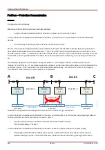
The following diagram is an example to clarify this problem: It can happen that in substation A the bays for
“Device 1.2” and “Device 2.1” are located quite close together and the two fiber optic cables are connected with the
same patch panel. If the connections have been swapped inadvertently – as shown in red color in the diagram –
the activation of the protection communication is not possible.
Example for a situation where setting the Pair ID helps to prevent wrong connections.
In menu
Protection Para/Global Prot Para/Prot-Transfer, select whether or not the Smart View operating software
shall be permitted to access the data of the remote device.
•
Set
Use remote access to “inactive” if the remote access shall be denied.
(The default setting is “active”.)
In menu
Protection Para/Global Prot Para/Prot-Transfer, define the required minimum transfer quality.
•
The setting
24h Err WarnLev defines the maximum number of ProtCom transmission errors that are
tolerated during 24 hours. Above this threshold, the device issues the warning message
Qual.-Warn.
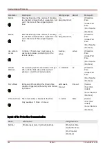
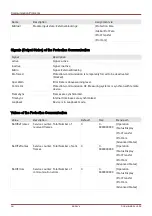
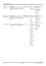
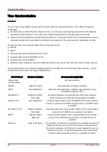
388
MCDLV4
DOK-HB-MCDLV4-2E
P
ro
tC
om
_Z
01
Device
1.1
A
B
C
Line A-B
Line B-C
Pair ID = 1
Pair ID = 2
A-B
patch panel
B-C
A-B B-C
wrong links
Fiber Optics
Fiber Optics
Device
1.2
Device
1.1
Device
1.2
patch panel
patch panel
Содержание HighPROtec MCDLV4
Страница 1: ...Manual Line Differential Protection MCDLV4 Software Version 3 4 a DOK HB MCDLV4 2E Revision A English...
Страница 3: ...Order Code Order Code 3 MCDLV4 DOK HB MCDLV4 2E...
Страница 47: ...Installation and Connection 47 MCDLV4 DOK HB MCDLV4 2E...
Страница 164: ...Input Output and LED Settings 164 MCDLV4 DOK HB MCDLV4 2E...
Страница 433: ...Parameters 433 MCDLV4 DOK HB MCDLV4 2E...
Страница 457: ...Device Parameters 457 MCDLV4 DOK HB MCDLV4 2E...
Страница 473: ...Blockings 473 MCDLV4 DOK HB MCDLV4 2E...
Страница 822: ...Protective Elements Name Description Profibus Scada Cmd 16 Scada Command 822 MCDLV4 DOK HB MCDLV4 2E...
Страница 988: ...Protective Elements 988 MCDLV4 DOK HB MCDLV4 2E P P Q P Q P Q Q Q P S S...
Страница 989: ...Protective Elements 989 MCDLV4 DOK HB MCDLV4 2E Pr Q P Q P Qr...
Страница 1023: ...Protective Elements 1023 MCDLV4 DOK HB MCDLV4 2E...
Страница 1070: ...Supervision 1070 MCDLV4 DOK HB MCDLV4 2E...

