Supervision
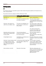
Self Supervision within the devices
Parameter Setting (Device)
Protecting the parameter setting by
plausibility checks.
Implausibilities within the parameter
configuration can be detected by
means of plausibility checks.
Detected implausibilities are
highlighted by a question mark
symbol. Please refer to chapter
parameter setting for detailed
information.
Quality of the power supply
A hardware circuit ensures that the
device can only be used, if the power
supply is in the range specified by
the technical data.
If the supply voltage is too low, the
device will not start up or it will be set
out of service respectively.
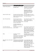
Sags of the supply voltage
Short-term sags of the supply
voltage are detected and can be
bridged in most of the cases by
means of the integrated buffer within
the power supply hardware.
This buffer also allows the
termination of ongoing data writing
procedures.
The module for the supervision of the
system utilization will detect
repetitive short-term sags of the
supply voltage.
Internal data of the device
(memory load, internal resources, ...)
An internal module monitors the
system utilization.
The module for the supervision of the
system utilization initiates in case of
a fatal error a reboot of the device. In
case of minor faults the System LED
will flash alternating red and green
(please refer to the
Troubleshooting
Guide). The issue will be recorded as
a system message.
Battery
The battery is monitored
continuously.
Notice: The battery serves as buffering of the
clock (real time clock). There's no impact on
the functionality of the device if the battery
breaks down, except for the buffering of the
clock while the unit is in de-energized
condition.
If the battery is low the System LED
will flash alternating red and green
(please refer to the
Troubleshooting
Guide).
Status of the device communication
(SCADA)
The projected and activated SCADA
module supervises its connection to
the master communication system.
You can check if there is active
communication with the master
system within menu <Operation/
Status display/ Communication>.
In order to monitor this state you can
assign this status onto an LED
and/or an output relay.
For details on the status of the
GOOSE communication please refer
to chapter IEC61850.
1094
MCDLV4
DOK-HB-MCDLV4-2E
Содержание HighPROtec MCDLV4
Страница 1: ...Manual Line Differential Protection MCDLV4 Software Version 3 4 a DOK HB MCDLV4 2E Revision A English...
Страница 3: ...Order Code Order Code 3 MCDLV4 DOK HB MCDLV4 2E...
Страница 47: ...Installation and Connection 47 MCDLV4 DOK HB MCDLV4 2E...
Страница 164: ...Input Output and LED Settings 164 MCDLV4 DOK HB MCDLV4 2E...
Страница 433: ...Parameters 433 MCDLV4 DOK HB MCDLV4 2E...
Страница 457: ...Device Parameters 457 MCDLV4 DOK HB MCDLV4 2E...
Страница 473: ...Blockings 473 MCDLV4 DOK HB MCDLV4 2E...
Страница 822: ...Protective Elements Name Description Profibus Scada Cmd 16 Scada Command 822 MCDLV4 DOK HB MCDLV4 2E...
Страница 988: ...Protective Elements 988 MCDLV4 DOK HB MCDLV4 2E P P Q P Q P Q Q Q P S S...
Страница 989: ...Protective Elements 989 MCDLV4 DOK HB MCDLV4 2E Pr Q P Q P Qr...
Страница 1023: ...Protective Elements 1023 MCDLV4 DOK HB MCDLV4 2E...
Страница 1070: ...Supervision 1070 MCDLV4 DOK HB MCDLV4 2E...

