


Protective Elements
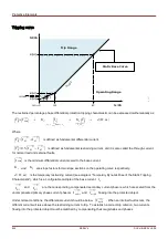
Setting the Tripping Curve
∣
I
dmin
∣
is the minimum differential current multiple scaled to the base current to get the restrained phase
differential protection to trip, which should be set based on the static error (no load error, transformer magnetizing
current, and measurement circuit noise).
K
1
and
K
2
are the restraining slopes that will be determined with
the settings
I
d
∣
I
s0
∣
,
I
d
∣
I
s1
∣
, and
I
d
∣
I
s2
∣
as follows:
K
1
=
∣
I
d
(
∣
⃗
I
s1
∣
)−
I
d
(
∣
⃗
I
s0
∣
)
∣
/
I
s1
K
2
=
∣
I
d
(
∣
⃗
I
s2
∣
)−
I
d
(
∣
⃗
I
s1
∣
)
∣
/(
I
s2
−
I
s1
)
All current settings are expressed as multiples of the base current (Ib). The base current will be calculated internally
from the power rating and voltage ratings of the protected object under the field parameter menu.
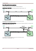
For generator or motor differential protection the base current is defined as:
I
b
=
S
N
√
3
⋅
V
LL
=
Rated Power
Generator
√
3
⋅
Rated Voltage
Generator
For step-up transformers with two windings the two base currents for each winding are defined respectively as:
I
b ,W1
=
S
N
√
3
⋅
V
LL,W1
I
b ,W2
=
S
N
√
3
⋅
V
LL,W2
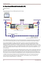
For setting the tripping characteristics of the 87 Transformer Phase Differential
Protection, the base current
I
b
=
I
b , W1
is to be used.
For the 87 (Line / Generator / Unit) Phase Differential Protection, the base
current
I
b
is to be used.
The procedures to configure:
I
d
∣
I
s0
∣
,
I
d
∣
I
s1
∣
, and
I
d
∣
I
s2
∣
:
1. Use
I
d
∣
I
s0
∣
as a minimum differential current to trip (starting point of the tripping characteristic is at
I
s0
= 0);
2. Select the slope
K
1
(usually around 15%-40% [typically 25%]);
3. Calculate set value
I
d
∣
I
s1
∣
using
I
d
∣
I
s0
∣
and
K
1
:
I
d
(
∣
⃗
I
s1
∣
)=
I
d
(
∣
⃗
I
s0
∣
)+
I
s1
⋅
K
1
;
4. Select the slope
K
2
(usually around 40%-90% [typically 60%]);
5. Calculate set value
I
d
∣
I
s2
∣
using
I
d
∣
I
s1
∣
and
K
2
:
I
d
(
∣
⃗
I
s2
∣
)=
I
d
(
∣
⃗
I
s1
∣
)+(
I
s2
−
I
s1
)
⋅
K
2
;
606
MCDLV4
DOK-HB-MCDLV4-2E
Содержание HighPROtec MCDLV4
Страница 1: ...Manual Line Differential Protection MCDLV4 Software Version 3 4 a DOK HB MCDLV4 2E Revision A English...
Страница 3: ...Order Code Order Code 3 MCDLV4 DOK HB MCDLV4 2E...
Страница 47: ...Installation and Connection 47 MCDLV4 DOK HB MCDLV4 2E...
Страница 164: ...Input Output and LED Settings 164 MCDLV4 DOK HB MCDLV4 2E...
Страница 433: ...Parameters 433 MCDLV4 DOK HB MCDLV4 2E...
Страница 457: ...Device Parameters 457 MCDLV4 DOK HB MCDLV4 2E...
Страница 473: ...Blockings 473 MCDLV4 DOK HB MCDLV4 2E...
Страница 822: ...Protective Elements Name Description Profibus Scada Cmd 16 Scada Command 822 MCDLV4 DOK HB MCDLV4 2E...
Страница 988: ...Protective Elements 988 MCDLV4 DOK HB MCDLV4 2E P P Q P Q P Q Q Q P S S...
Страница 989: ...Protective Elements 989 MCDLV4 DOK HB MCDLV4 2E Pr Q P Q P Qr...
Страница 1023: ...Protective Elements 1023 MCDLV4 DOK HB MCDLV4 2E...
Страница 1070: ...Supervision 1070 MCDLV4 DOK HB MCDLV4 2E...