Protective Elements
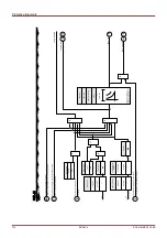
I2> and %I2/I1> – Unbalanced Load [46]
Elements:
I2>[1] ,I2>[2]
The
I2>
Current Unbalance module works similar to the
V 012
Voltage Unbalance module. The positive and
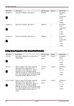
negative sequence currents are calculated from the 3-phase currents. The threshold setting (either »
I2>«
or
»I
2/FLA«)
defines a minimum operating current magnitude of I2 for the 46 function to operate, which insures that
the relay has a solid basis for initiating a current unbalance trip. The »
%(I2/I1)«
(option) setting is the unbalance trip
pickup setting. It is defined by the ratio of negative sequence current to positive sequence current »
%(I2/I1)«
.
All I2>
Current Unbalance module
s are identically structured.
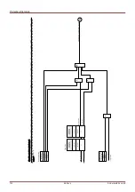
The condition for a trip of this module is that the negative sequence current I2 is above the set threshold
and
–
if
configured
–
the percentage current unbalance is above the setting
»
%(I2/I1)«. The module initiates a trip if this
condition is fulfilled for a specific tripping delay time.
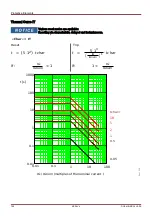
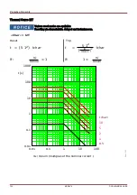
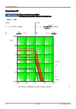
For this tripping delay time, there are two characteristics available as configuring options, a definite time
characteristic (DEFT, where the tripping delay is a setting value) and an inverse characteristic (INV, where the
tripping delay is calculated).
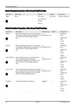
The setting of
»CurrentBase
« decides about whether
»
I2>«
or
»I
2/FLA« is used as the threshold value. This rating
value
–
»
I2>«
or
»I
2/FLA«
–
is the permitted continuous unbalanced load current, and it is specified in units of either
I
n
(for
»
CurrentBase
« = “Device Rating”) or I
b
(for
»
CurrentBase
« = “Protected Object Rating”).
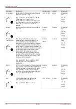
The principle of the definite time characteristic (DEFT) is as follows:
•
The module trips if for the tripping delay time (which is set as the Setting Group parameter
»t
«) the negative
sequence current I2 is above the set threshold
and (if configured) the percentage current unbalance is
above the setting
»
%(I2/I1)«.
The principle of the inverse time characteristic (INV) is as follows:
•
The protective device permanently calculates the heat (thermal) energy
θ of the object to be protected. This
happens all the time, independent of any alarm or tripping decisions.
The module trips if for the tripping delay time
t
trip
–
which is dependent on
θ
–
the following conditions are all
fulfilled:
1. The negative sequence current
I2 is above the set threshold
(»
I2>«
or
»I
2/FLA«) and
2. the percentage current unbalance is above the setting
»
%(I2/I1)« (if
»
%(I2/I1)« is set to active) and
3. the calculated thermal energy
θ exceeds a maximum value θ
max
,, which is calculated based on the
setting
K for the thermal load capability.
•
For
θ = 0 the tripping delay time is calculated as follows:
for
»
CurrentBase
« = “Device Rating”
for
»
CurrentBase
« = “Protected Object Rating”
t
A
=
K
⋅
I
n
2
I
2
2
−
I
2
›
2
t
A
=
K
⋅
I
b
2
I
2
2
−
I
2
⁄ FLA
2
where
t
trip
= tripping delay in seconds,
743
MCDLV4
DOK-HB-MCDLV4-2E
Содержание HighPROtec MCDLV4
Страница 1: ...Manual Line Differential Protection MCDLV4 Software Version 3 4 a DOK HB MCDLV4 2E Revision A English...
Страница 3: ...Order Code Order Code 3 MCDLV4 DOK HB MCDLV4 2E...
Страница 47: ...Installation and Connection 47 MCDLV4 DOK HB MCDLV4 2E...
Страница 164: ...Input Output and LED Settings 164 MCDLV4 DOK HB MCDLV4 2E...
Страница 433: ...Parameters 433 MCDLV4 DOK HB MCDLV4 2E...
Страница 457: ...Device Parameters 457 MCDLV4 DOK HB MCDLV4 2E...
Страница 473: ...Blockings 473 MCDLV4 DOK HB MCDLV4 2E...
Страница 822: ...Protective Elements Name Description Profibus Scada Cmd 16 Scada Command 822 MCDLV4 DOK HB MCDLV4 2E...
Страница 988: ...Protective Elements 988 MCDLV4 DOK HB MCDLV4 2E P P Q P Q P Q Q Q P S S...
Страница 989: ...Protective Elements 989 MCDLV4 DOK HB MCDLV4 2E Pr Q P Q P Qr...
Страница 1023: ...Protective Elements 1023 MCDLV4 DOK HB MCDLV4 2E...
Страница 1070: ...Supervision 1070 MCDLV4 DOK HB MCDLV4 2E...

