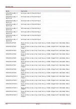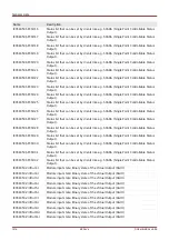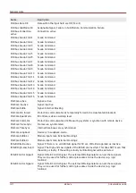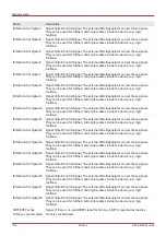
General Lists
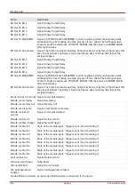
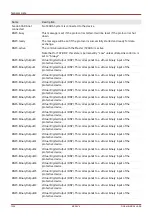
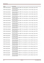
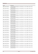
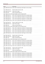
Name
Description
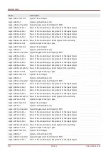
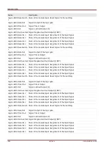
Statistics.ResFc all
Signal: Resetting of all Statistic values (Current Demand, Power Demand, Min, Max)
Statistics.ResFc Vavg
Signal: Resetting of the sliding average calculation.
Statistics.ResFc I
Demand
Signal: Resetting of Statistics - Current Demand (avg, peak avg)
Statistics.ResFc P
Demand
Signal: Resetting of Statistics - Power Demand (avg, peak avg)
Statistics.ResFc Max
Signal: Resetting of all Maximum values
Statistics.ResFc Min
Signal: Resetting of all Minimum values
Statistics.StartFc Vavg-I State of the module input: Start of Statistics Average Voltage
Statistics.StartFc I
Demand-I
State of the module input: Start of the Statistics of the Current Demand
Statistics.StartFc P
Demand-I
State of the module input: Start of the Statistics of the Active Power Demand
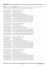
Logics.LE1.Gate Out
Signal: Output of the logic gate
Logics.LE1.Timer Out
Signal: Timer Output
Logics.LE1.Out
Signal: Latched Output (Q)
Logics.LE1.Out inverted
Signal: Negated Latched Output (Q NOT)
Logics.LE1.Gate In1-I
State of the module input: Assignment of the Input Signal
Logics.LE1.Gate In2-I
State of the module input: Assignment of the Input Signal
Logics.LE1.Gate In3-I
State of the module input: Assignment of the Input Signal
Logics.LE1.Gate In4-I
State of the module input: Assignment of the Input Signal
Logics.LE1.Reset Latch-I State of the module input: Reset Signal for the Latching
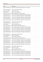
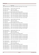
Logics.LE2.Gate Out
Signal: Output of the logic gate
Logics.LE2.Timer Out
Signal: Timer Output
Logics.LE2.Out
Signal: Latched Output (Q)
Logics.LE2.Out inverted
Signal: Negated Latched Output (Q NOT)
Logics.LE2.Gate In1-I
State of the module input: Assignment of the Input Signal
Logics.LE2.Gate In2-I
State of the module input: Assignment of the Input Signal
Logics.LE2.Gate In3-I
State of the module input: Assignment of the Input Signal
Logics.LE2.Gate In4-I
State of the module input: Assignment of the Input Signal
Logics.LE2.Reset Latch-I State of the module input: Reset Signal for the Latching
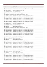
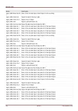
Logics.LE3.Gate Out
Signal: Output of the logic gate
Logics.LE3.Timer Out
Signal: Timer Output
Logics.LE3.Out
Signal: Latched Output (Q)
Logics.LE3.Out inverted
Signal: Negated Latched Output (Q NOT)
Logics.LE3.Gate In1-I
State of the module input: Assignment of the Input Signal
Logics.LE3.Gate In2-I
State of the module input: Assignment of the Input Signal
Logics.LE3.Gate In3-I
State of the module input: Assignment of the Input Signal
Logics.LE3.Gate In4-I
State of the module input: Assignment of the Input Signal
Logics.LE3.Reset Latch-I State of the module input: Reset Signal for the Latching
Logics.LE4.Gate Out
Signal: Output of the logic gate
1219
MCDLV4
DOK-HB-MCDLV4-2E
Содержание HighPROtec MCDLV4
Страница 1: ...Manual Line Differential Protection MCDLV4 Software Version 3 4 a DOK HB MCDLV4 2E Revision A English...
Страница 3: ...Order Code Order Code 3 MCDLV4 DOK HB MCDLV4 2E...
Страница 47: ...Installation and Connection 47 MCDLV4 DOK HB MCDLV4 2E...
Страница 164: ...Input Output and LED Settings 164 MCDLV4 DOK HB MCDLV4 2E...
Страница 433: ...Parameters 433 MCDLV4 DOK HB MCDLV4 2E...
Страница 457: ...Device Parameters 457 MCDLV4 DOK HB MCDLV4 2E...
Страница 473: ...Blockings 473 MCDLV4 DOK HB MCDLV4 2E...
Страница 822: ...Protective Elements Name Description Profibus Scada Cmd 16 Scada Command 822 MCDLV4 DOK HB MCDLV4 2E...
Страница 988: ...Protective Elements 988 MCDLV4 DOK HB MCDLV4 2E P P Q P Q P Q Q Q P S S...
Страница 989: ...Protective Elements 989 MCDLV4 DOK HB MCDLV4 2E Pr Q P Q P Qr...
Страница 1023: ...Protective Elements 1023 MCDLV4 DOK HB MCDLV4 2E...
Страница 1070: ...Supervision 1070 MCDLV4 DOK HB MCDLV4 2E...

