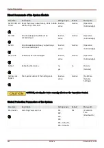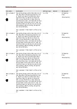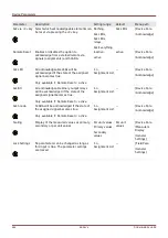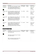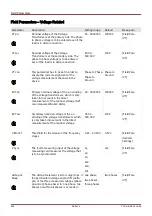
Device Parameters
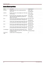
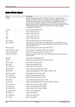
System Module Signals
Signal
Description
Reboot
Signal: Rebooting the device: 1=Normal Start-up; 2=Reboot by the
Operator; 3=Reboot by means of Super Reset; 4=outdated; 5=outdated;
6=Unknown Error Source; 7=Forced Reboot (initiated by the main
processor); 8=Exceeded Time Limit of the Protection Cycle; 9= Forced
Reboot (initiated by the digital signal processor); 10=Exceeded Time Limit
of the Measured Value Processing; 11=Sags of the Supply Voltage;
12=Illegal Memory Access.
Act Set
Signal: Active Parameter Set
PS 1
Signal: Parameter Set 1
PS 2
Signal: Parameter Set 2
PS 3
Signal: Parameter Set 3
PS 4
Signal: Parameter Set 4
PSS manual
Signal: Manual Switch over of a Parameter Set
PSS via Scada
Signal: Parameter Set Switch via Scada. Write into this output byte the
integer of the parameter set that should become active (e.g. 4 => Switch
onto parameter set 4).
PSS via Inp fct
Signal: Parameter Set Switch via input function
min 1 param changed
Signal: At least one parameter has been changed
Setting Lock Bypass
Signal: Short-period unlock of the Setting Lock
Param to be saved
Number of parameters to be saved. 0 means that all parameter changes
are overtaken.
Ack LED
Signal: LEDs acknowledgement
Ack BO
Signal: Acknowledgement of the Binary Outputs
Ack Counter
Signal: Reset of all Counters
Ack Scada
Signal: Acknowledge Scada
Ack TripCmd
Signal: Reset Trip Command
Ack LED-HMI
Signal: LEDs acknowledgement :HMI
Ack BO-HMI
Signal: Acknowledgement of the Binary Outputs :HMI
Ack Counter-HMI
Signal: Reset of all Counters :HMI
Ack Scada-HMI
Signal: Acknowledge Scada :HMI
Ack TripCmd-HMI
Signal: Reset Trip Command :HMI
Ack LED-Sca
Signal: LEDs acknowledgement :SCADA
Ack BO-Sca
Signal: Acknowledgement of the Binary Outputs :SCADA
Ack Counter-Sca
Signal: Reset of all Counters :SCADA
Ack Scada-Sca
Signal: Acknowledge Scada :SCADA
Ack TripCmd-Sca
Signal: Reset Trip Command :SCADA
Res OperationsCr
Signal:: Res OperationsCr
Res AlarmCr
Signal:: Res AlarmCr
Res TripCmdCr
Signal:: Res TripCmdCr
Res TotalCr
Signal:: Res TotalCr
456
MCDLV4
DOK-HB-MCDLV4-2E
Содержание HighPROtec MCDLV4
Страница 1: ...Manual Line Differential Protection MCDLV4 Software Version 3 4 a DOK HB MCDLV4 2E Revision A English...
Страница 3: ...Order Code Order Code 3 MCDLV4 DOK HB MCDLV4 2E...
Страница 47: ...Installation and Connection 47 MCDLV4 DOK HB MCDLV4 2E...
Страница 164: ...Input Output and LED Settings 164 MCDLV4 DOK HB MCDLV4 2E...
Страница 433: ...Parameters 433 MCDLV4 DOK HB MCDLV4 2E...
Страница 457: ...Device Parameters 457 MCDLV4 DOK HB MCDLV4 2E...
Страница 473: ...Blockings 473 MCDLV4 DOK HB MCDLV4 2E...
Страница 822: ...Protective Elements Name Description Profibus Scada Cmd 16 Scada Command 822 MCDLV4 DOK HB MCDLV4 2E...
Страница 988: ...Protective Elements 988 MCDLV4 DOK HB MCDLV4 2E P P Q P Q P Q Q Q P S S...
Страница 989: ...Protective Elements 989 MCDLV4 DOK HB MCDLV4 2E Pr Q P Q P Qr...
Страница 1023: ...Protective Elements 1023 MCDLV4 DOK HB MCDLV4 2E...
Страница 1070: ...Supervision 1070 MCDLV4 DOK HB MCDLV4 2E...


