Protective Elements
Connection Groups
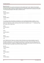
W1 Connection/Grounding
This is the setting for the connection scheme of the winding W1 and its grounding condition.
Allowed Settings
Default (example)
Y, D, Z, YN, ZN
Y
W2 Connection/Grounding
This is the setting for the connection scheme of the winding W2 and its grounding condition.
Allowed Settings
Default (example)
y, d, z, yn, zn
y
The combination of W1 Connection/Grounding and W2 Winding/Grounding allows for all possible physical
connection schemes of stepup transformers. The N or n can be set whenever the neutral of the transformer is
connected to ground and the grid on that side of the winding is grounded.
Phase Shift:
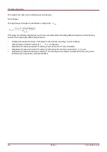
Phase shift in multiples of 0...11 * (-30) degree that the secondary voltage lags the primary voltage.
Default (example)
0 (0 degrees )
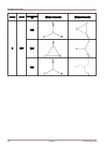
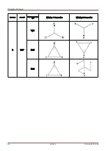
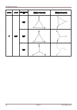
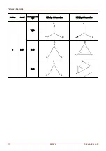
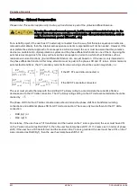
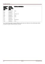
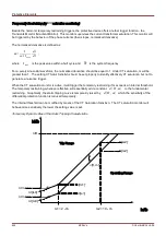
Please refer to the Phase Compensation section for a number of typical, preferred transformer types.
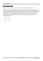
For (Y, y, Z, z) connections, the neutral can be connected to ground or not connected to ground. In general, there is
a distinction between odd (1, 3, 5, …, 11) and even (0, 2, 4, …,10) connection numbers. Together with the
connection scheme (y, d, or z) and the treatment of the neutral of the transformer, the following definitions are
taken.
•
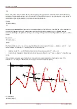
The three-phase symmetrical system I1 is rotated counter-clockwise when transferring from winding 1 to
winding 2 (applies for ABC phase sequence).
•
The three-phase symmetrical system I2 is rotated clockwise when transferring from winding 1 to winding 2.
(applies for ABC phase sequence).
•
The connection of the transformer to a negative rotating system (ACB) is taken into account according to the
parameter.
•
The transformation of the zero sequence system I0 depends on the connection of the windings:
–
Only (Y, y, Z, z) – connections provide for an external available neutral point;
–
Only when this neutral point is connected to ground (this is indicated by an appended „n“ in the winding
group setting (example Dyn)), and at least another ground connection is available
on the grid to which the winding is connected (a zero sequence - respectively ground current can flow);
and
–
Only when both windings of the transformer allow for ground current flowing, the zero sequence current
can be transformed from one side of the transformer to the other without any phase shift.
•
Odd connection groups are created by Dy, Yd, Yz, Zy schemes.
•
Even connection groups are created by Yy, Zd, Dz, Dd.
•
The primary values of winding 1 are reference values when displaying or evaluating relative values.
628
MCDLV4
DOK-HB-MCDLV4-2E
Содержание HighPROtec MCDLV4
Страница 1: ...Manual Line Differential Protection MCDLV4 Software Version 3 4 a DOK HB MCDLV4 2E Revision A English...
Страница 3: ...Order Code Order Code 3 MCDLV4 DOK HB MCDLV4 2E...
Страница 47: ...Installation and Connection 47 MCDLV4 DOK HB MCDLV4 2E...
Страница 164: ...Input Output and LED Settings 164 MCDLV4 DOK HB MCDLV4 2E...
Страница 433: ...Parameters 433 MCDLV4 DOK HB MCDLV4 2E...
Страница 457: ...Device Parameters 457 MCDLV4 DOK HB MCDLV4 2E...
Страница 473: ...Blockings 473 MCDLV4 DOK HB MCDLV4 2E...
Страница 822: ...Protective Elements Name Description Profibus Scada Cmd 16 Scada Command 822 MCDLV4 DOK HB MCDLV4 2E...
Страница 988: ...Protective Elements 988 MCDLV4 DOK HB MCDLV4 2E P P Q P Q P Q Q Q P S S...
Страница 989: ...Protective Elements 989 MCDLV4 DOK HB MCDLV4 2E Pr Q P Q P Qr...
Страница 1023: ...Protective Elements 1023 MCDLV4 DOK HB MCDLV4 2E...
Страница 1070: ...Supervision 1070 MCDLV4 DOK HB MCDLV4 2E...

