Supervision
CTS -
Current Transformer Supervision [60L]
Available elements:
CTS
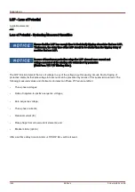
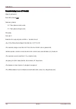
Wire breaks and failures within measuring circuits cause current transformer failures.
The module
»CTS« can detect a failure of the CT if the calculated earth current does not match the measured one.
If an adjustable threshold value (Difference of measured and calculated earth current) is exceeded, a CT failure can
be assumed. This is signaled through a message/alarm.
The precondition is that the conductor currents are measured by the device and the earth current, for instance, by a
ring core type current transformer.
The measuring principles of the circuit supervision are based on comparing the measured and the calculated
residual currents:
In an ideal case these are:
IL1
IL2
IL3
KI
∗
IG
=
3
∗
I
0
KI
∗
IG
=
0
KI represents a correction factor which takes the different transformation ratio of the phase- and earth current
transformers into account. The device automatically calculates this factor from the rated field parameters, i.e. the
relation between the rated primary and secondary current values of the phase- and earth current transformers.
For compensating the current proportional ratio error of the measuring circuits, the dynamic correction factor Kd can
be used. As a function of the measured max. current this factor is considering the linear rising measuring error.
The limiting value of the CT supervision is calculated as follows:
∆
I = deviation I (rated value)
Kd = correction factor
Imax = current maximum
Limiting value =
∆
I + Kd x Imax
Precondition for identifying an error
3
∗
I
0
KI
∗
IG
Delta I
Kd
∗
Imax
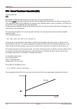
The evaluation method of the circuit supervision by using factor Kd can be graphically represented as follows:
1074
MCDLV4
DOK-HB-MCDLV4-2E
limit value
Imax
I
Kd*Imax
Содержание HighPROtec MCDLV4
Страница 1: ...Manual Line Differential Protection MCDLV4 Software Version 3 4 a DOK HB MCDLV4 2E Revision A English...
Страница 3: ...Order Code Order Code 3 MCDLV4 DOK HB MCDLV4 2E...
Страница 47: ...Installation and Connection 47 MCDLV4 DOK HB MCDLV4 2E...
Страница 164: ...Input Output and LED Settings 164 MCDLV4 DOK HB MCDLV4 2E...
Страница 433: ...Parameters 433 MCDLV4 DOK HB MCDLV4 2E...
Страница 457: ...Device Parameters 457 MCDLV4 DOK HB MCDLV4 2E...
Страница 473: ...Blockings 473 MCDLV4 DOK HB MCDLV4 2E...
Страница 822: ...Protective Elements Name Description Profibus Scada Cmd 16 Scada Command 822 MCDLV4 DOK HB MCDLV4 2E...
Страница 988: ...Protective Elements 988 MCDLV4 DOK HB MCDLV4 2E P P Q P Q P Q Q Q P S S...
Страница 989: ...Protective Elements 989 MCDLV4 DOK HB MCDLV4 2E Pr Q P Q P Qr...
Страница 1023: ...Protective Elements 1023 MCDLV4 DOK HB MCDLV4 2E...
Страница 1070: ...Supervision 1070 MCDLV4 DOK HB MCDLV4 2E...

