Unit Startup
RT-SVX24J-EN
163
Thermostatic Expansion Valves
The reliability and performance of the refrigeration system
is heavily dependent upon proper expansion valve
adjustment.Therefore, the importance of maintaining the
proper superheat cannot be over emphasized.
On air-cooled units, the expansion valves shipped
installed were factory set to control between 14-18°F at the
ARI full load rating conditions (approximately 45°/125°F
saturated suction/discharge). On evaporative condenser
units, the expansion valves shipped installed were factory
set to control between 18-22°F at the ARI full load rating
conditions (approximately 45°/105°F saturated suction/
discharge). At part load, expect lower superheat. Systems
operating with lower superheat could cause serious
compressor damage due to refrigerant floodback.
Pressure curves, included in the IOM, are based on
outdoor ambient between 65° & 105°F, relative humidity
above 40 percent. Measuring the operating pressures can
be meaningless outside of these ranges.
Measuring Superheat
1.
Measure the suction pressure at the suction line gauge
access port located near the compressor.
2. Using a Refrigerant/Temperature chart, convert the
pressure reading to a corresponding saturated vapor
temperature.
3. Measure the suction line temperature as close to the
expansion valve bulb, as possible. Use a thermocouple
type probe for an accurate reading.
4. Subtract the saturated vapor temperature obtained in
step 2 from the actual suction line temperature
obtained in step 3. The difference between the two
temperatures is known as “superheat”.
When adjusting superheat, recheck the system subcooling
before shutting the system “Off”.
Note:
If unit includes the modulating reheat
dehumidification option, adjust superheat only in
the cooling mode of operation.
Charging by Subcooling
The outdoor ambient temperature must be between 65
and 105°F and the relative humidity of the air entering the
evaporator must be above 40 percent. When the
temperatures are outside of these ranges, measuring the
operating pressures can be meaningless. Make sure hot
gas bypass (if applicable) is not flowing when taking
performance measurements. With the unit operating at
“Full Circuit Capacity”, acceptable subcooling ranges for
air-cooled units is between 14°F to 22°F.
For evaporative condenser units, acceptable subcooling
range is between 8°F to 14°F.
Measuring Subcooling
1. At the liquid line service valve, measure the liquid line
pressure. Using a Refrigerant R410A pressure/
temperature chart, convert the pressure reading into
the corresponding saturated temperature.
2. Measure the actual liquid line temperature as close to
the liquid line service valve as possible. To ensure an
accurate reading, clean the line thoroughly where the
temperature sensor will be attached. After securing the
sensor to the line, insulate the sensor and line to isolate
it from the ambient air. Use a thermocouple type probe
for an accurate reading.
Note:
Glass thermometers do not have sufficient contact
area to give an accurate reading.
3. Determine the system subcooling by subtracting the
actual liquid line temperature (measured in step 2)
from the saturated liquid temperature (converted in
step 1).
Standard Ambient Units
The following Table gives the minimum starting
temperatures for Standard Ambient Units. Do not start the
unit in the cooling mode if the ambient temperature is
below the recommended operating temperatures.
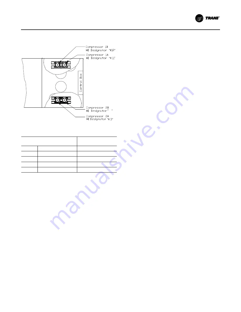
Figure 115. Compressor locations and staging sequence
Table 46. Staging sequence
Compressor Staging
(Lead)
Compressor Staging
(Lag)
1A
1B
2A
2B
1A
1B
2A
2B
Stage 1
X
X
Stage 2
X
X
X
X
Stage 3
X
X
X
X
X
X
Stage 4
X
X
X
X
X
X
X
X
K4
Содержание SEHJ090-162
Страница 40: ...Dimensional Data 40 RT SVX24J EN Figure 13 Evaporative condenser water connection locations RIGHT SIDE VIEW ...
Страница 48: ...Installation 48 RT SVX24J EN Figure 18 Ductwork conversion ...
Страница 58: ...Installation 58 RT SVX24J EN Figure 36 5 Connected tubes 6 install panels Connected tubes 5 6 ...
Страница 75: ...Installation RT SVX24J EN 75 Figure 51 Hot water coil piping Figure 52 Steam coil piping ...
Страница 87: ...Installation RT SVX24J EN 87 Figure 57 Typical field wiring diagram for 90 to 162 ton CV control options ...
Страница 89: ...Installation RT SVX24J EN 89 Figure 59 Typical field wiring diagram for 90 to 162 ton VAV control options ...


