Options 3-21
Diskette Drive Options
The diskette drive controller is incorporated into the system board. The controller contains
the circuitry and control functions needed to support one or two diskette drives. In the
Image P90E and Image P100E, a 3 1/2-inch, 1.44-MB diskette drive is standard equipment.
The standard diskette drive cable-connects to the system board at connector J2. To add a
second, optional diskette drive, a single cable with two drive connectors is required. This
dual-connector ribbon cable plugs directly into the system board at connector J2 in place of
the standard cable. It can be purchased as an option from NEC or from your dealer or other
computer hardware distributor.
The first diskette drive (3 1/2-inch) is drive A, while the second, optional diskette drive is
drive B. See the 5 1/4-inch device installation instructions later in this section when
installing an optional diskette drive. See Section 4 for information on ordering optional
equipment.
Diskette Drive Settings
Specifications for the standard 3 1/2-inch, 1.44-MB and the optional 5 1/4-inch, 1.2-MB
diskette drive are given in Appendix A, Specifications. The standard 1.44-MB diskette
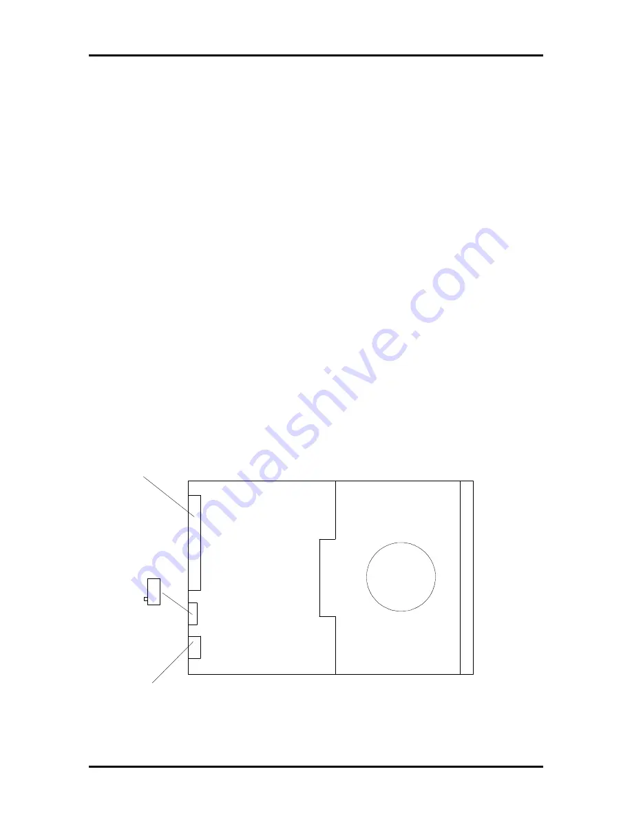
drive setting is shown in Figure Section 3-15. The settings for the optional 1.2-MB diskette
drive are shown in Figure Section 3-16.
When installing two diskette drives, both diskette drives are addressed to drive 1. The
terminating resistor jumper should not be removed from the 5 1/4-inch diskette. Both
diskette drives (the standard and the optional) are normally terminated.
Figure Section 3-15 3 1/2-Inch, 1.44-MB Diskette Drive
Power Connector
Signal Connector
Front
of Drive
DS SW1


