


3-4 Options
Expansion Board(s)
Expansion boards plug into edge connectors on the EISA/PCI-bus slots.
There are three 16-bit EISA/ISA slots, one shared EISA/PCI-bus expansion slot, and one
dedicated PCI-bus slot. See Appendix B for EISA and PCI connector pin assignments.
Install expansion boards into the system unit as follows.
1.
Remove the top cover as previously described.
2.
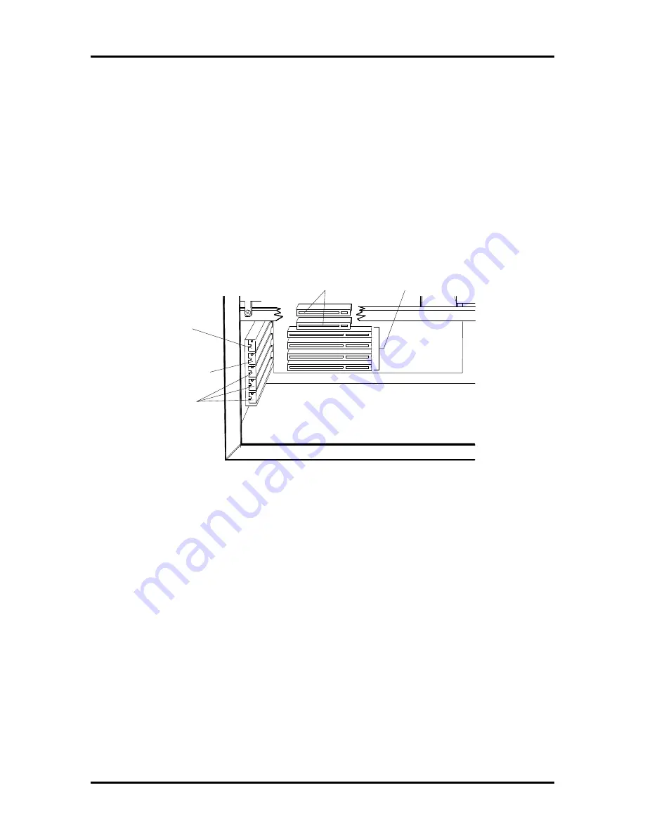
Remove the expansion slot screw and cover (see Figure Section 3-3). Save the
expansion slot cover in the event the expansion board is removed in the future.
Figure Section 3-3 Expansion Slots
3.
Install the expansion board into an expansion slot connector. When installing a
full-size expansion board, make sure that the expansion board slides into the
guide rail at the front of the system unit.
4.
Reinstall the expansion slot screw to secure the expansion board.
5.
Connect any expansion board cables.
6.
Replace the top cover.
PCI/EISA
Shared Slot
PCI Slot
PCI/EISA Slots (3)
Connectors
PCI
Connectors
EISA/ISA