Options 3-17
n
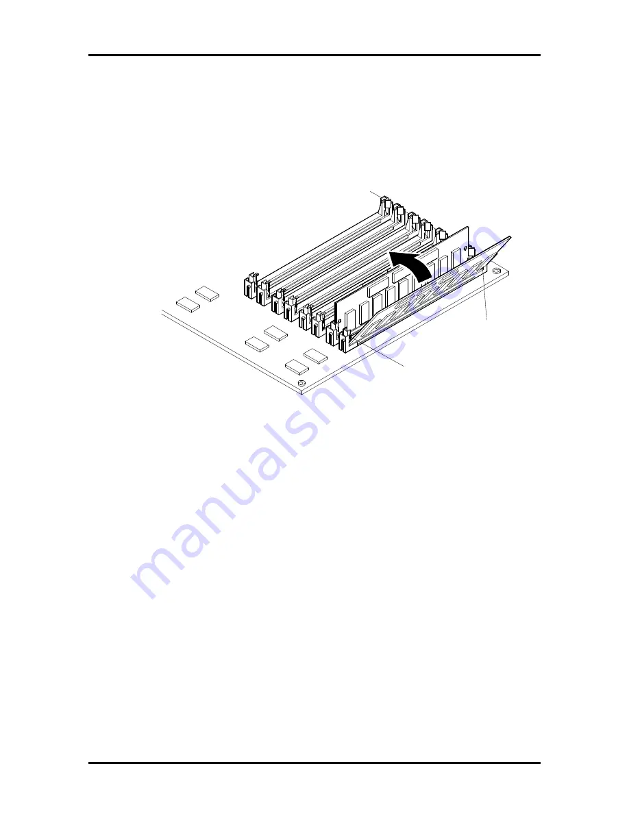
Align the notched end of the SIMM with the correct end of the SIMM socket
and insert it at an angle into the socket (see Figure Section 3-12).
n
Carefully push the SIMM towards the metal clips. Using equal pressure at the
ends of the SIMM, push it until it locks under the metal clips at the ends of
the socket.
Figure Section 3-12 Inserting the SIMM
6.
Repeat step 5 for each SIMM to be installed.
7.
With the SIMMs facing down, install the memory expansion board in the system
unit as follows.
n
Position the memory expansion board under the bracket bar (see ).
n
Align the memory expansion board edge connector with the memory
expansion board connector (J9) on the system board (see Figure Section 3-4).
n
Carefully insert the memory expansion board into the connector. You may
have to gently rock the board from side to side to seat it into the connector.
n
Fasten the memory expansion board to the bracket bar with the two
previously removed screws.
Clip
Notched End
of SIMM


