4-115
MELFA-BASIC V functions
4MELFA-BASIC V
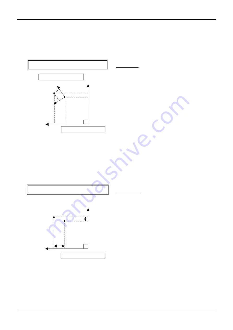
(2) Relative calculation of position data (multiplication)
Numerical variables are calculated by the usual four arithmetic operations. The calculation of position vari-
ables involves coordinate conversions, however, not just the four basic arithmetic operations. This is
explained using simple examples.
An example of relative calculation (multiplication)
1 P2=(10,5,0,0,0,0)(0,0)
2 P100=P1*P2
3 Mov P1
4 Mvs P100
P1=(200,150,100,0,0,45)(4,0)
In this example, the hand tip is moved relatively within the
P1 tool coordinate system at teaching position P1. The
values of the X and Y coordinates of P2 become the
amount of movement within the tool coordinate system.
The relative calculation is given by multiplication of the P
variables. Be aware that the result becomes different if the
order of multiplication is different. The variable that speci-
fies the amount of relative movement (P2) should be
entered lastly.
If the posture axis parts of P2 (A, B, and C) are 0, the pos-
ture of P1 is used as is. If there are non-zero values avail-
able, the new posture is determined by rotating the hand
around the Z, Y, and X axes (in the order of C, B, and A)
relative to the posture of P1. Multiplication corresponds to
addition within the tool coordinate system, while division
corresponds to subtraction within the tool coordinate sys-
tem.
(3) Relative calculation of position data (Addition)
An example of relative calculation(Addition)
1 P2=(5,10,0,0,0,0)(0,0)
2 P100=P1+P2
3 Mov P1
4 Mvs P100
P1=(200,150,100,0,0,45)(4,0)
In this example, the hand is moved relatively within the
robot coordinate system at teaching position P1. The val-
ues of the X and Y coordinates of P2 become the amount
of movement within the robot coordinate system. The rela-
tive calculation is given by addition of the P variables.
If a value is entered for the C-axis coordinate of P2, it is
possible to change the C-axis coordinate of P100. The
resulting value will be the sum of the C-axis coordinate of
P1 and the C-axis coordinate of P2.
CAUTION)
In the example above, the explanation is made in two dimensions for the sake of simplicity. In actuality, the
calculation is made in three dimensions. In addition, the tool coordinate system changes depending on the
posture.
X
Y
X1
Y1
P1
5mm
10mm
P100
M ultip lication b etween P variab les
(relative calculation in the tool coord inate system )
Tool coord inate system at P1
Rob ot coord inate system
X
Y
P1
P100
10mm
5mm
Ad d ition of P variab les
(relative calculation in the rob ot coord inate system )
Rob ot coord inate system


