8-4
MM2 Motor Manager 2
GE Power Management
8.3 CONFIGURATION
8 MM2PC
®
SOFTWARE
8
8.3 CONFIGURATION
8.3.1 CONFIGURING MM2PC
®
1. Connect a GE Power Management RS232/485 converter module to the COM1 or COM2 PC port
and wire the RS485 +/– terminals on the box to MM2 terminals 25/26. Be careful to observe cor-
rect polarity of the RS485 connections. See Figure 2–6: RS485 TERMINATION on page 2–7 for
connection details.
2. Start the MM2PC
®
software. MM2PC
®
will attempt to communicate with the MM2. The MM2 to
PC communications status is displayed on the bottom right of the MM2PC
®
window.
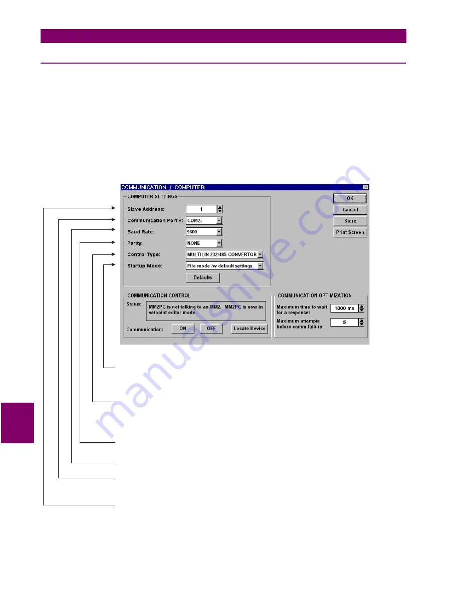
3. To configure communications, select the Communications > Computer menu item. The COM-
MUNICATION / COMPUTER window appears containing the various communications settings
for the local PC. Modify these settings as shown below:
Figure 8–2: COMMUNICATION / COMPUTER WINDOW
Set the
based on user preference. In “Communicate with Relay” mode, MM2PC will attempt
to establish communications immediately upon startup. While in the “File mode /w default settings”, MM2PC
waits for the user to click the ON button before attempting communications – this mode is preferred when
the MM2PC is being used without an attached MM3.
Startup Mode
Set
to match the type of RS232/RS485 converter. If connected through the MM2 front panel
RS232 port, select “No Control Type”. If connected through a GE Power Management F485 converter unit,
select “MULTILIN RS232/RS485 CONVERTOR”. If connected through a modem, select “Modem”. If a third-
party RS232/RS485 converter is being used, select the appropriate control type from the available list based
on the manufacturer’s specifications.
Control Type
Set
to match the
setpoint. If connected through the MM2
front panel RS232 port, set to “None”.
Parity
S1 CONFIGURATION \ COMMUNICATIONS \ PARITY
Set
to match the
setpoint.
Baud Rate
S1 CONFIGURATION \ COMMUNICATIONS \ BAUD RATE
Set
to
where the MM2 is connected (e.g. COM1
or COM2). On most computers, COM1 is used by the mouse device and as such COM2 is usually
available for communications.
Communcation Port #
the COM port on your local PC
Set
to match the
setpoint.
Slave Address
S1 CONFIGURATION \ COMMUNICATIONS \ COMMUNICATIONS ADDRESS
Содержание MOTOR MANAGER 2
Страница 2: ......
Страница 4: ......
Страница 21: ...GE Power Management MM2 Motor Manager 2 2 3 2 INSTALLATION 2 1 MOUNTING 2 Figure 2 4 TYPICAL WIRING DIAGRAM ...
Страница 33: ...GE Power Management MM2 Motor Manager 2 3 7 3 HARDWARE 3 3 THEORY OF OPERATION 3 Figure 3 2 BLOCK DIAGRAM ...
Страница 34: ...3 8 MM2 Motor Manager 2 GE Power Management 3 3 THEORY OF OPERATION 3 HARDWARE 3 ...
Страница 80: ...5 12 MM2 Motor Manager 2 GE Power Management 5 5 A4 STATISTICS 5 ACTUAL VALUES 5 ...
Страница 130: ...7 2 MM2 Motor Manager 2 GE Power Management 7 1 INJECTION TESTING 7 TESTING 7 Figure 7 1 SECONDARY INJECTION TEST SETUP ...
Страница 153: ...GE Power Management MM2 Motor Manager 2 9 5 9 STARTER TYPES 9 2 FV REVERSING STARTER 9 Figure 9 4 FV REVERSING STARTER ...
Страница 161: ...GE Power Management MM2 Motor Manager 2 9 13 9 STARTER TYPES 9 4 SLIP RING STARTER 9 Figure 9 10 SLIP RING STARTER ...
Страница 187: ...GE Power Management MM2 Motor Manager 2 9 39 9 STARTER TYPES 9 13 SOFT STARTER 9 Figure 9 25 SOFT STARTER ...
Страница 188: ...9 40 MM2 Motor Manager 2 GE Power Management 9 13 SOFT STARTER 9 STARTER TYPES 9 ...
Страница 212: ...E 4 MM2 Motor Manager 2 GE Power Management E 1 CT ISOLATION APPENDIXE E ...
Страница 220: ...iv MM2 Motor Manager 2 GE Power Management INDEX ...


