


5.3 Description of Function Codes
5-63
FU
NCT
IO
N
C
O
DE
S
Chap 5
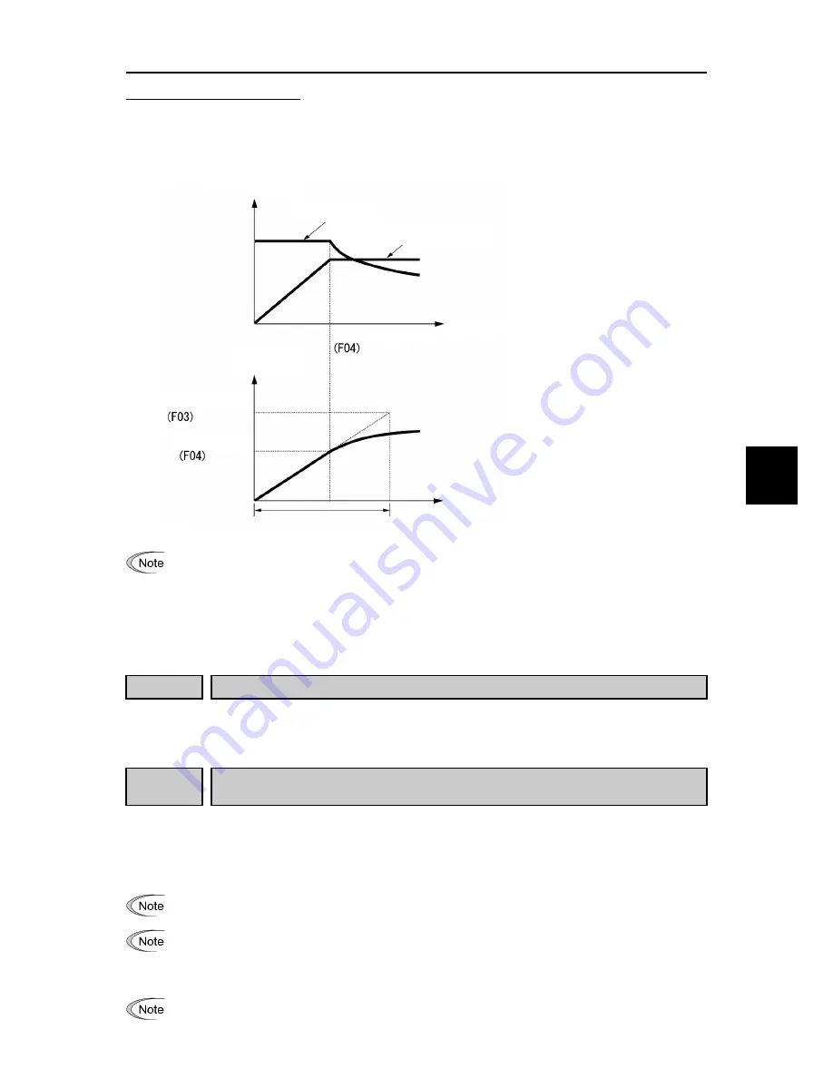
Curve acceleration/deceleration
This is a pattern to perform linear acceleration/deceleration (rated torque) at or below base frequency and
acceleration becomes gradually slower at or higher than the base frequency, and acceleration/deceleration with
constant load rate (rated output).
It is possible to accelerate/decelerate with the maximum capability of the motor to be driven by the inverter.
•
When S-curve acceleration/deceleration and curve acceleration/deceleration is selected by curve
acceleration/deceleration H07, the actual acceleration/deceleration time becomes longer than the set
value.
•
If acceleration/deceleration time is set shorter than necessary, current limiting function, torque limit or
anti-regenerative function may operate and acceleration/deceleration time may become longer than
the set value.
F09
Torque boost 1
(Refer to F37)
For details of torque boost 1 setting, refer to the section of function code F37.
F10 to F12 Electronic thermal overload Protection for motor 1 (Select motor characteristics,
Thermal time constant)
In order to detect overload of motor (electronic thermal function by inverter output current), set temperature
characteristics of motor (Select motor characteristics (F10), thermal time constant (F12), and overload detection
level (F11).
When overload of motor is detected, inverter is turned off, protecting the motor with motor overload alarm
0l1
.
Improper setting of the electronic thermal function may result in a failure to protect the motor from
burning.
Temperature characteristics of motor is used for motor overload early warning “OL” as well. Even if only
overload early warning is used, it is necessary to set temperature characteristics of the motor (F10, F12).
(
Function code E34)
For disabling motor overload alarm, set F11 = 0.00 (Disable).
For PTC thermistor built-in motor, by connecting PTC thermistor to terminal [C1], it is possible to protect
the motor. Refer to H26 to find the details.
Torque/output
Acceleration torque
Acceleration output (kW)
Specified acceleration time
Time
Base frequency
Output frequency
Output frequency
Maximum frequency
Base frequency
The diagram on the left shows
pattern at acceleration.
This is the same as at deceleration.
Содержание FRENIC-Ace series
Страница 20: ......
Страница 32: ......
Страница 92: ......
Страница 94: ......
Страница 452: ......
Страница 490: ......
Страница 504: ......
Страница 506: ...8 2 Frequency Setting Section 8 2 8 2 Frequency Setting Section Figure 8 2 1 Frequency Setting Section Block Diagram...
Страница 508: ...8 2 Frequency Setting Section 8 4 Figure 8 2 3 Frequency Setting Section Block Diagram...
Страница 514: ...8 6 Control Section 8 10 3 With speed sensor Figure 8 6 3 V f Control with speed sensor Section Block Diagram...
Страница 520: ...8 6 Control Section 8 16 6 For PMSM Figure 8 6 9 Vector Control For PMSM Section Block Diagram...
Страница 522: ...8 7 FM Output Section 8 18 8 7 FM Output Section Figure 8 7 1 FM Output Section Block Diagram...
Страница 582: ......
Страница 646: ...11 9 Power Regenerative PWM Converters RHC Series 11 42 11 9 5 External dimensions PWM converter Boosting reactor...
Страница 649: ...11 9 Power Regenerative PWM Converters RHC Series 11 45 SELECTING PERIPHERAL EQUIPMENT Chap 11 Charging resistor Fuse...
Страница 664: ...11 15 External Cooling Fan Attachments 11 60...
Страница 690: ......
Страница 692: ......
Страница 720: ......
Страница 738: ......
Страница 787: ......


