


4.6 Selecting a Desired Motor Drive Control
4-8
4.6 Selecting a Desired Motor Drive Control
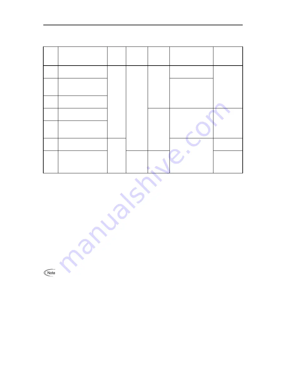
The FRENIC-Ace supports the following motor drive control.
F42*
data
Drive control
Basic
control
Applicable
Motor type
Speed
feedback
Speed control
For
configuration,
refer to:
0
V/f control with slip
compensation inactive
V/f
control
IM
Disable
Frequency control
4.8.1 [ 1 ]
4.8.1 [ 2 ]
1
Vector control without
speed sensor (Dynamic
torque vector)
Frequency control
with slip
compensation
2
V/f control with slip
compensation active
3
V/f Control with speed
sensor
Enable
Frequency control
with ASR (Auto speed
regulator)
4.8.1 [ 3 ]
4
V/f Control with speed
sensor (with Auto Torque
Boost)
6
Vector Control with
speed sensor
Vector
control
Speed control with
automatic speed
regulator (ASR)
4.8.1 [ 4 ]
15
Vector Control without
speed sensor and
magnetic pole position
sensor
PM
Estimated
Speed
4.8.2 [ 1 ]
4.8.2 [ 2 ]
4.8.2 [ 3 ]
4.6.1 V/f control with slip compensation inactive for IM
Under this control, the inverter controls a motor with the voltage and frequency according to the V/f pattern specified
by function codes. This control disables all automatically controlled features such as the slip compensation, so no
unpredictable output fluctuation results, enabling stable operation with constant output frequency.
4.6.2 Vector control without speed sensor (Dynamic torque vector) for IM
To get the maximal torque out of a motor, this control calculates the motor torque for the load applied and uses it to
optimize the voltage and current vector output.
Selecting this control automatically enables the auto torque boost and slip compensation function.
This control is effective for improving the system response to external disturbances such as load fluctuation, and the
motor speed control accuracy.
Note that the inverter may not respond to a rapid load fluctuation since this control is an open-loop V/f control that
does not perform the current control, unlike the vector control. The advantages of this control include larger
maximum torque per output current than that the vector control.
Since slip compensation and vector control without speed sensor (dynamic torque vector) use motor
parameters, the following conditions should be satisfied; otherwise, full control performance may not be
obtained.
•
A single motor should be controlled per inverter.
•
Motor parameters P02*, P03*, and P06* to P13* should be properly configured or auto-tuning (P04*)
should be performed.
•
The capacity of the motor to be controlled should not be two or more ranks lower (based on the HHD
mode) than that of the inverter under the vector control without speed sensor (dynamic torque vector).
Otherwise, the inverter may not control the motor due to decrease of the current detection resolution.
The wiring distance between the inverter and motor should be 50 m (164 ft) or less. If it is longer, the
inverter may not control the motor due to leakage current flowing through stray capacitance to the
ground or between wires. Especially, small capacity inverters whose rated current is also small may be
unable to control the motor correctly even when the wiring is less than 50 m (164 ft). In that case, make
the wiring length as short as possible or use a wire with small stray capacitance (e.g., loosely-bundled
cable) to minimize the stray capacitance.
Содержание FRENIC-Ace series
Страница 20: ......
Страница 32: ......
Страница 92: ......
Страница 94: ......
Страница 452: ......
Страница 490: ......
Страница 504: ......
Страница 506: ...8 2 Frequency Setting Section 8 2 8 2 Frequency Setting Section Figure 8 2 1 Frequency Setting Section Block Diagram...
Страница 508: ...8 2 Frequency Setting Section 8 4 Figure 8 2 3 Frequency Setting Section Block Diagram...
Страница 514: ...8 6 Control Section 8 10 3 With speed sensor Figure 8 6 3 V f Control with speed sensor Section Block Diagram...
Страница 520: ...8 6 Control Section 8 16 6 For PMSM Figure 8 6 9 Vector Control For PMSM Section Block Diagram...
Страница 522: ...8 7 FM Output Section 8 18 8 7 FM Output Section Figure 8 7 1 FM Output Section Block Diagram...
Страница 582: ......
Страница 646: ...11 9 Power Regenerative PWM Converters RHC Series 11 42 11 9 5 External dimensions PWM converter Boosting reactor...
Страница 649: ...11 9 Power Regenerative PWM Converters RHC Series 11 45 SELECTING PERIPHERAL EQUIPMENT Chap 11 Charging resistor Fuse...
Страница 664: ...11 15 External Cooling Fan Attachments 11 60...
Страница 690: ......
Страница 692: ......
Страница 720: ......
Страница 738: ......
Страница 787: ......


