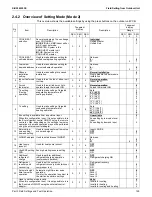
Field Setting from Outdoor Unit
SiUS342303E
193
Part 5 Field Settings and Test Operation
77
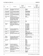
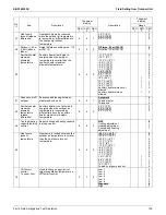
VRTsmart
control
Tc lower limit
Used to change lower limit of target
condensation temperature in
VRTsmart control.
2.
7
7
Low
Standard
High 1
High 2
High 3
High 4
High 5
High 6
0
1
2
3
4
5
6
7
78
VRT control
Te upper limit
Used to change upper limit of
target evaporation temperature in
VRT control.
2.
7
8
Standard
High
4
6
79
VRT control
Tc lower limit
Used to change lower limit of target
condensation temperature in VRT
control.
2.
7
9
Standard
Low
2
3
81
Cooling comfort
setting
Cooling comfort setting
2.
8
1
Eco
Mild
Quick
Powerful
0
1
2
3
82
Heating comfort
setting
Heating comfort setting
2.
8
2
Eco
Mild
Quick
Powerful
0
1
2
3
83
Master user
interface
allocation in
case
VRV
indoor
units and
Mini-split indoor
units are used at
the same time
By changing this setting, you can
allow the
VRV
indoor unit to be the
operation mode selector (system
power OFF/ON is required after
applying this setting).
2.
8
3
VRV
indoor unit has mode
selection right
Mini-split indoor unit has
mode selection right
0
1
87
Intermittent fan
operation
Used for intermittent fan operation
setting.
2.
8
7
OFF
30 minutes OFF, 1 minute ON
with medium fan speed
30 minutes OFF, 1 minute ON
with high fan speed
0
1
2
90
Indoor unit
without power
Multi-tenant function setting
2.
9
0
Invalid
Valid (No U4 error generation)
Valid (Operating with U4
warning)
0
1
2
No.
1
Item
Description
7 segment
display
Description
7 segment
display
Range
SEG
1
SEG
2
SEG
3
SEG
1
SEG
2
SEG
3
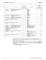
1: Numbers in the "No." column represent the number of times to press the BS button.
: Setting does not return to factory setting when exit mode 2. To cancel the function, change
setting manually to factory setting.
: Once function is activated
t01
appears. To stop current function, press once the
RETURN
(BS3)
button. For detailed description about each setting, refer to
Details of Setting Mode 2
on page 194.
Indication
bold underline
means factory setting.
Содержание VRV EMERION RXYQ-AATJA
Страница 1: ...Service Manual Heat Pump 60 Hz RXYQ AATJA 208 230 V RXYQ AAYDA 460 V SiUS342303E...
Страница 380: ...Check SiUS342303E 373 Part 6 Service Diagnosis Reference Reference CHECK 7 Refer to page 379 CHECK 8 Refer to page 380...
Страница 405: ...SiUS342303E Wiring Diagrams Part 7 Appendix 398 RXYQ72 96 120 144 168 192 216 240AAYDA C 2D140769B...
Страница 406: ...Wiring Diagrams SiUS342303E 399 Part 7 Appendix 1 2 Indoor Unit FXFQ07 09 12 15 18 24 30 36 48TVJU 3D086460B...
Страница 407: ...SiUS342303E Wiring Diagrams Part 7 Appendix 400 BYCQ125BGW1 Self Cleaning Decoration Panel for FXFQ TVJU 3D076375A...
Страница 410: ...Wiring Diagrams SiUS342303E 403 Part 7 Appendix FXEQ07 09 12 15 18 24PVJU 3D098557A...
Страница 411: ...SiUS342303E Wiring Diagrams Part 7 Appendix 404 FXDQ07 09 12 18 24MVJU C 3D050501C...
Страница 413: ...SiUS342303E Wiring Diagrams Part 7 Appendix 406 FXMQ07 09 12 15 18 24 30 36 48 54PBVJU 3D093209B...
Страница 416: ...Wiring Diagrams SiUS342303E 409 Part 7 Appendix FXHQ12 24 36MVJU 3D048116C...
Страница 417: ...SiUS342303E Wiring Diagrams Part 7 Appendix 410 FXAQ07 09 12 18 24PVJU 3D075354F...
Страница 423: ...SiUS342303E Wiring Diagrams Part 7 Appendix 416 1 3 2 Energy Recovery Ventilator VAM Series VAM300 470 600GVJU 3D073269D...
Страница 424: ...Wiring Diagrams SiUS342303E 417 Part 7 Appendix VAM1200GVJU 3D073270D...


