


SiUS342303E
Field Setting from Outdoor Unit
Part 5 Field Settings and Test Operation
208
When heat pump lockout mode has been set the auto backup function will automatically be set.
This will allow the auxiliary or secondary heat source to be automatically energized in the event of a
system failure.
Error codes capable of auto backup are listed in the table below.
Please be aware that the error codes that are not listed do not auto backup in order to protect the
unit.
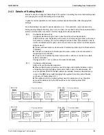
[2-47]: Heat pump lockout release differential
Heat pump would be resumed when the outdoor air temperature is recovered by differential
(below) above the heat pump lockout temperature.
Heat pump lockout
release differential
Fahrenheit (°F)
Celsius (°C)
0
5
2.8
1 (default)
10
5.6
2
15
8.3
Error contents
Error code
(Auto backup possible)
Activation of high pressure switch
E3
Activation of low pressure sensor
E4
Compressor motor lock
E5
Compressor damage alarm
E6
Outdoor fan motor abnormality
E7
Electronic expansion valve coil abnormality
E9
Position signal abnormality of outdoor unit fan motor
H3
H7
Outdoor air thermistor abnormality
H9
Discharge pipe temperature abnormality
F3
Wet alarm
F4
Discharge pipe thermistor abnormality
Compressor body thermistor abnormality
J3
Suction pipe thermistor abnormality
J5
Heat exchanger deicer thermistor abnormality
Heat exchanger gas pipe thermistor abnormality
J6
Subcooling heat exchanger liquid pipe thermistor abnormality
J7
Heat exchanger liquid pipe thermistor abnormality
J8
Subcooling heat exchanger gas pipe thermistor abnormality
Electrical box air outlet thermistor abnormality
J9
High pressure sensor abnormality
JA
Low pressure sensor abnormality
JC
Inverter PCB abnormality
L1
Radiation fin temperature rise abnormality
L4
Compressor instantaneous overcurrent
L5
Compressor overcurrent
L8
Compressor startup abnormality
L9
Transmission error between inverter and outdoor unit main PCB
LC
Содержание VRV EMERION RXYQ-AATJA
Страница 1: ...Service Manual Heat Pump 60 Hz RXYQ AATJA 208 230 V RXYQ AAYDA 460 V SiUS342303E...
Страница 380: ...Check SiUS342303E 373 Part 6 Service Diagnosis Reference Reference CHECK 7 Refer to page 379 CHECK 8 Refer to page 380...
Страница 405: ...SiUS342303E Wiring Diagrams Part 7 Appendix 398 RXYQ72 96 120 144 168 192 216 240AAYDA C 2D140769B...
Страница 406: ...Wiring Diagrams SiUS342303E 399 Part 7 Appendix 1 2 Indoor Unit FXFQ07 09 12 15 18 24 30 36 48TVJU 3D086460B...
Страница 407: ...SiUS342303E Wiring Diagrams Part 7 Appendix 400 BYCQ125BGW1 Self Cleaning Decoration Panel for FXFQ TVJU 3D076375A...
Страница 410: ...Wiring Diagrams SiUS342303E 403 Part 7 Appendix FXEQ07 09 12 15 18 24PVJU 3D098557A...
Страница 411: ...SiUS342303E Wiring Diagrams Part 7 Appendix 404 FXDQ07 09 12 18 24MVJU C 3D050501C...
Страница 413: ...SiUS342303E Wiring Diagrams Part 7 Appendix 406 FXMQ07 09 12 15 18 24 30 36 48 54PBVJU 3D093209B...
Страница 416: ...Wiring Diagrams SiUS342303E 409 Part 7 Appendix FXHQ12 24 36MVJU 3D048116C...
Страница 417: ...SiUS342303E Wiring Diagrams Part 7 Appendix 410 FXAQ07 09 12 18 24PVJU 3D075354F...
Страница 423: ...SiUS342303E Wiring Diagrams Part 7 Appendix 416 1 3 2 Energy Recovery Ventilator VAM Series VAM300 470 600GVJU 3D073269D...
Страница 424: ...Wiring Diagrams SiUS342303E 417 Part 7 Appendix VAM1200GVJU 3D073270D...