


Refrigerant Circuit (Piping Diagrams)
SiUS342303E
45
Part 2 Refrigerant Circuit
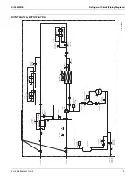
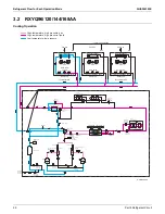
1.3 Indoor Low-Temperature Hydrobox
HXY48TAVJU*
No. in piping
diagram
Name
Symbol
Function
(1)
Pump
M1P
Circulates water to the local water piping and radiator. It
operates at a maximum of 4,800 rpm.
(2)
Flow switch
S1L
Detects an abnormality in the water circuit. If the flow rate of
water is below a certain value, an error will be issued.
(3)
Electronic expansion valve
K1E
In cooling operation, the superheating at the outlet of the
plate-type heat exchanger is controlled to be constant.
(4)
Thermistor
(outlet water temperature)
R1T
Detects the outlet water temperature of the plate-type heat
exchanger. It is used for thermo-off judgment.
(5)
Thermistor
(inlet water temperature)
R2T
Detects the inlet water temperature of the plate-type heat
exchanger.
(6)
Thermistor
(refrigerant liquid pipe)
R3T
Detects the liquid pipe temperature of the plate-type heat
exchanger. It is used to judge the freeze-up prevention
control in cooling operation.
(7)
Thermistor
(refrigerant gas pipe)
R4T
Detects the gas pipe temperature of the plate-type heat
exchanger.
(8)
Plate-type heat exchanger
—
Exchanges heat between refrigerant and water.
3D079034
G
N
I
L
P
U
O
C
K
C
I
U
Q
.
N
N
O
C
D
E
Z
A
R
B
E
V
L
A
V
K
C
E
H
C
.
N
N
O
C
E
R
A
L
F
SPINNED PIPE
E
P
I
P
D
E
H
C
N
I
P
.
N
N
O
C
E
G
N
A
L
F
SCREW CONN.
PLATE HEAT EXCHANGER
EVAPORATOR =
CONDENSOR =
REFR.IN
REFR.OUT
REFR.IN
REFR.OUT
R4T
R2T
R1T
R3T
WATER INLET
WATER OUTLET
WATER SIDE
REFRIGERANT SIDE
FILTER
FILTER
FILTER
FILTER
EXPANSION
VALVE
FLOWSWITCH
AIR PURGE
SHUT OFF VALVE WITH
DRAIN/FILL VALVE
FIELD INSTALLED
SHUT OFF VALVE WITH
DRAIN/FILL VALVE
FIELD INSTALLED
EXPANSION
VESSEL
PUMP
SAFETY VALVE
MANOMETER
THERMISTOR DESCRIPTION
R1T
OUTLET WATER HEAT EXCHANGER THERMISTOR
R2T
INLET WATER HEAT EXCHANGER THERMISTOR
R3T
REFRIGERANT LIQUID SIDE THERMISTOR
R4T
REFRIGERANT GAS SIDE THERMISTOR
(2)
(4)
(7)
(8)
(3)
(6)
(5)
(1)
Содержание VRV EMERION RXYQ-AATJA
Страница 1: ...Service Manual Heat Pump 60 Hz RXYQ AATJA 208 230 V RXYQ AAYDA 460 V SiUS342303E...
Страница 380: ...Check SiUS342303E 373 Part 6 Service Diagnosis Reference Reference CHECK 7 Refer to page 379 CHECK 8 Refer to page 380...
Страница 405: ...SiUS342303E Wiring Diagrams Part 7 Appendix 398 RXYQ72 96 120 144 168 192 216 240AAYDA C 2D140769B...
Страница 406: ...Wiring Diagrams SiUS342303E 399 Part 7 Appendix 1 2 Indoor Unit FXFQ07 09 12 15 18 24 30 36 48TVJU 3D086460B...
Страница 407: ...SiUS342303E Wiring Diagrams Part 7 Appendix 400 BYCQ125BGW1 Self Cleaning Decoration Panel for FXFQ TVJU 3D076375A...
Страница 410: ...Wiring Diagrams SiUS342303E 403 Part 7 Appendix FXEQ07 09 12 15 18 24PVJU 3D098557A...
Страница 411: ...SiUS342303E Wiring Diagrams Part 7 Appendix 404 FXDQ07 09 12 18 24MVJU C 3D050501C...
Страница 413: ...SiUS342303E Wiring Diagrams Part 7 Appendix 406 FXMQ07 09 12 15 18 24 30 36 48 54PBVJU 3D093209B...
Страница 416: ...Wiring Diagrams SiUS342303E 409 Part 7 Appendix FXHQ12 24 36MVJU 3D048116C...
Страница 417: ...SiUS342303E Wiring Diagrams Part 7 Appendix 410 FXAQ07 09 12 18 24PVJU 3D075354F...
Страница 423: ...SiUS342303E Wiring Diagrams Part 7 Appendix 416 1 3 2 Energy Recovery Ventilator VAM Series VAM300 470 600GVJU 3D073269D...
Страница 424: ...Wiring Diagrams SiUS342303E 417 Part 7 Appendix VAM1200GVJU 3D073270D...