SiUS342303E
Field Setting from Outdoor Unit
Part 5 Field Settings and Test Operation
202
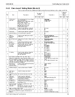
[2-31]:
Power consumption limitation level (step 2) via the external control adaptor
(DTA104A62)
If the system needs to run under power consumption limitation conditions when an
external signal is sent to the unit, this setting defines the level power consumption
limitation that will be applied for step 2. The level is according to the table.
Default value: 1
Change [2-31] to 1, 2 or 3 in function of required limitation.
Value
[2-31]
Power consumption limitation (approximately)
1 (default)
40%
2
50%
3
55%
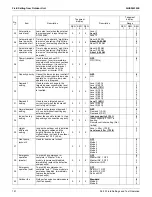
[2-32]:
Forced, all time, power consumption limitation operation (no external control adaptor
is required to perform power consumption limitation)
If the system always needs to run under power consumption limitation conditions,
this setting activates and defines the level power consumption limitation that will be
applied continuously. The level is according to the table.
Default value: 0 (OFF).
Value
[2-32]
Restriction reference
0 (default)
Function not active
1
Follows [2-30] setting
2
Follows [2-31] setting
Change [2-32]: 0,1 or 2 in function of required limitation.
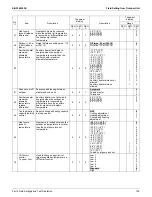
[2-34]:
Indoor fan tap setting
Indoor units fan speed limitation related to connection capacity and outdoor air
temperature for energy saving
Value
[2-34]
Indoor fan tap setting
0 (default)
Fan speed is limited to L tap when indoor units capacity
130%.
1
In heating mode, fan speed is limited to L tap when indoor units capacity
130%.
2
Fan speed follows the setting of remote controllers (not limited by indoor units
connection capacity).
[2-35]:
Height difference setting
Default value: 1
In case the outdoor unit is installed in the lowest position (indoor units are installed on a
higher position than outdoor units) and the height difference between the highest indoor
unit and the outdoor unit exceeds 40 m (130 ft), the setting [2-35] should be changed to
0.
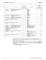
[2-38]:
Emergency operation “Master”
To disable compressor operation permanently: in case of single module or “Master” unit
of a multi outdoor system, this setting allows:
Default value: 0. Compressor operation enabled.
Field setting:
Set 1: Master INV. 1 is disabled permanently.
Set 2: Master INV. 2 is disabled permanently
Set 3: Master module is disabled permanently.
Содержание VRV EMERION RXYQ-AATJA
Страница 1: ...Service Manual Heat Pump 60 Hz RXYQ AATJA 208 230 V RXYQ AAYDA 460 V SiUS342303E...
Страница 380: ...Check SiUS342303E 373 Part 6 Service Diagnosis Reference Reference CHECK 7 Refer to page 379 CHECK 8 Refer to page 380...
Страница 405: ...SiUS342303E Wiring Diagrams Part 7 Appendix 398 RXYQ72 96 120 144 168 192 216 240AAYDA C 2D140769B...
Страница 406: ...Wiring Diagrams SiUS342303E 399 Part 7 Appendix 1 2 Indoor Unit FXFQ07 09 12 15 18 24 30 36 48TVJU 3D086460B...
Страница 407: ...SiUS342303E Wiring Diagrams Part 7 Appendix 400 BYCQ125BGW1 Self Cleaning Decoration Panel for FXFQ TVJU 3D076375A...
Страница 410: ...Wiring Diagrams SiUS342303E 403 Part 7 Appendix FXEQ07 09 12 15 18 24PVJU 3D098557A...
Страница 411: ...SiUS342303E Wiring Diagrams Part 7 Appendix 404 FXDQ07 09 12 18 24MVJU C 3D050501C...
Страница 413: ...SiUS342303E Wiring Diagrams Part 7 Appendix 406 FXMQ07 09 12 15 18 24 30 36 48 54PBVJU 3D093209B...
Страница 416: ...Wiring Diagrams SiUS342303E 409 Part 7 Appendix FXHQ12 24 36MVJU 3D048116C...
Страница 417: ...SiUS342303E Wiring Diagrams Part 7 Appendix 410 FXAQ07 09 12 18 24PVJU 3D075354F...
Страница 423: ...SiUS342303E Wiring Diagrams Part 7 Appendix 416 1 3 2 Energy Recovery Ventilator VAM Series VAM300 470 600GVJU 3D073269D...
Страница 424: ...Wiring Diagrams SiUS342303E 417 Part 7 Appendix VAM1200GVJU 3D073270D...


