


Symptom-based Troubleshooting
SiUS342303E
227
Part 6 Service Diagnosis
6
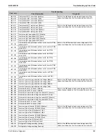
COOL/HEAT
selection is
disabled.
The remote controller displays
CENTRAL CONTROL.
This remote controller has no option
to select cooling operation.
Use a remote controller with option to
select cooling operation.
The remote controller displays
CENTRAL CONTROL,
and the
COOL/HEAT selection remote
controller is provided.
COOL/HEAT selection is made using
the COOL/HEAT selection remote
controller.
Use the COOL/HEAT selection
remote controller to select cool or
heat.
7
The system
conducts fan
operation but not
cooling or heating
operation.
This symptom occurs
immediately after turning ON
the power supply.
The system is in preparation mode of
operation.
Wait for a period of approximately 10
minutes.
The remote controller displays
CENTRAL CONTROL;
no
cooling or heating operation is
performed. Switch to fan
operation.
In thermal storage operation, the unit
is set to fan operation in cooling or
heating operation, and the remote
controller shows
CENTRAL
CONTROL.
Normal operation.
8
The airflow rate is
not reproduced
according to the
setting.
Even pressing the airflow rate
setting button makes no
changes in the airflow rate.
In heating operation, when the room
temperature reaches the set degree,
the outdoor unit will stop while the
indoor unit is brought to fan LL
operation so that no one gets cold air.
Furthermore, if fan operation mode is
selected when other indoor unit is in
heating operation, the system will be
brought to fan LL operation.
Normal operation.
9
The airflow
direction is not
reproduced
according to the
setting.
The airflow direction is not
corresponding to that displayed
on the remote controller.
The flap does not swing.
Automatic control
Normal operation.
10
A white mist
comes out from
the system.
Indoor unit
In cooling operation, the
ambient humidity is high.
(This indoor unit is installed in a
place with much oil or dust.)
Uneven temperature distribution due
to heavy stain of the inside of the
indoor unit
Clean the inside of the indoor unit.
Indoor unit
Immediately after cooling
operation stopping, the indoor
air temperature and humidity
are low.
Hot gas (refrigerant) that has flowed
in the indoor unit results to be vapor
from the unit.
Normal operation.
Indoor and outdoor units
After the completion of defrost
operation, the system is
switched to heating operation.
Defrosted moisture turns to be vapor
and comes out from the units.
Normal operation.
Symptom
Supposed Cause
Countermeasure
Содержание VRV EMERION RXYQ-AATJA
Страница 1: ...Service Manual Heat Pump 60 Hz RXYQ AATJA 208 230 V RXYQ AAYDA 460 V SiUS342303E...
Страница 380: ...Check SiUS342303E 373 Part 6 Service Diagnosis Reference Reference CHECK 7 Refer to page 379 CHECK 8 Refer to page 380...
Страница 405: ...SiUS342303E Wiring Diagrams Part 7 Appendix 398 RXYQ72 96 120 144 168 192 216 240AAYDA C 2D140769B...
Страница 406: ...Wiring Diagrams SiUS342303E 399 Part 7 Appendix 1 2 Indoor Unit FXFQ07 09 12 15 18 24 30 36 48TVJU 3D086460B...
Страница 407: ...SiUS342303E Wiring Diagrams Part 7 Appendix 400 BYCQ125BGW1 Self Cleaning Decoration Panel for FXFQ TVJU 3D076375A...
Страница 410: ...Wiring Diagrams SiUS342303E 403 Part 7 Appendix FXEQ07 09 12 15 18 24PVJU 3D098557A...
Страница 411: ...SiUS342303E Wiring Diagrams Part 7 Appendix 404 FXDQ07 09 12 18 24MVJU C 3D050501C...
Страница 413: ...SiUS342303E Wiring Diagrams Part 7 Appendix 406 FXMQ07 09 12 15 18 24 30 36 48 54PBVJU 3D093209B...
Страница 416: ...Wiring Diagrams SiUS342303E 409 Part 7 Appendix FXHQ12 24 36MVJU 3D048116C...
Страница 417: ...SiUS342303E Wiring Diagrams Part 7 Appendix 410 FXAQ07 09 12 18 24PVJU 3D075354F...
Страница 423: ...SiUS342303E Wiring Diagrams Part 7 Appendix 416 1 3 2 Energy Recovery Ventilator VAM Series VAM300 470 600GVJU 3D073269D...
Страница 424: ...Wiring Diagrams SiUS342303E 417 Part 7 Appendix VAM1200GVJU 3D073270D...