


SiUS342303E
Refrigerant Circuit (Piping Diagrams)
Part 2 Refrigerant Circuit
38
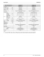
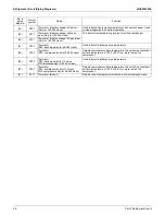
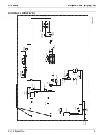
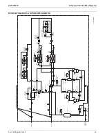
1. Refrigerant Circuit (Piping Diagrams)
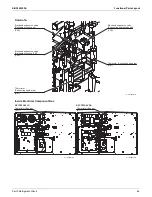
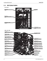
1.1 Outdoor
Unit
No. in
piping
diagram
Electric
symbol
Name
Function
(1)
M1C
Compressor 1
Compressor is operated in multi-steps according to Te or Tc by
using inverter.
(2)
M2C
Compressor 2 (Only for 96-240 class)
(3)
M1F
Fan motor 1
The fan rotation speed is varied by using inverter.
(4)
M2F
Fan motor 2 (Only for 96-240 class)
(5)
Y1E
Electronic expansion valve
(Heat exchanger main)
(Right side for 192-240 class)
While being used as evaporator, PI control is applied to keep the
outlet superheating degree of air heat exchanger constant.
(6)
Y2E
Electronic expansion valve
(Refrigerant cooling IPM)
Used to control the refrigerant flow to cool the diode bridge and
power module of the inverter PCB.
(7)
Y3E
Electronic expansion valve
(Subcooling heat exchanger)
PI control is applied to keep the outlet superheating degree of
subcooling heat exchanger constant.
(8)
Y4E
Electronic expansion valve
(Refrigerant auto charge)
Used to control refrigerant charging speed during refrigerant auto
charge operation and to stop refrigerant charge automatically.
(9)
Y5E
Electronic expansion valve
(Refrigerant cooling air)
Used to control the refrigerant flow to cool the air inside the
electrical component box.
(10)
Y6E
Electronic expansion valve
(Heat exchanger left)
(Only for 192-240 class)
While being used as evaporator, PI control is applied to keep the
outlet superheating degree of air heat exchanger constant.
(11)
Y1S
Solenoid valve
(Oil separator oil return 1 for 72 class,
Oil separator oil return 2 for 96-240 class)
Used to return oil from the oil separator to the compressor.
(12)
Y2S
Solenoid valve
(Oil separator oil return 1 for 96-240 class)
(13)
Y3S
Solenoid valve (Hot gas bypass)
Used to bypass high pressure gas at the bottom of the outdoor
heat exchanger.
(14)
Y4S
Solenoid valve (Accumulator oil return)
Used to return oil from the accumulator to the compressor.
(15)
Y5S
Solenoid valve (Four way valve)
Used to switch outdoor heat exchanger to evaporator or
condenser.
(16)
Y6S
Solenoid valve (Injection)
Used to control compressor injection.
(17)
S1NPH High pressure sensor
Used to detect the high pressure.
(18)
S1NPL Low pressure sensor
Used to detect the low pressure.
(19)
S1PH
High pressure switch (M1C)
This functions when pressure increases to stop operation and
avoid high pressure increase in the fault operation.
(20)
S2PH
High pressure switch (M2C)
(21)
—
Pressure regulating valve (Liquid pipe)
This is used when pressure increases, to prevent any damage on
components caused by pressure increase in transport or storage.
(22)
—
Subcooling heat exchanger
Apply subcooling to liquid refrigerant.
(23)
—
Capillary tube
Used to return the refrigerating oil separated through the oil
separator to the compressor.
(24)
—
Capillary tube
(25)
R1T
Thermistor (Outdoor air)
Used to detect outdoor air temperature, correct discharge pipe
temperature and for other purposes.
(26)
R2T
Thermistor (Heat exchanger liquid pipe)
(Right side for 192-240 class)
This detects temperature of liquid pipe for air heat exchanger.
(27)
R3T
Thermistor (Heat exchanger deicer)
(Right side for 192-240 class)
Used to detect liquid pipe temperature of air heat exchanger. Used
to make judgements on defrost operation.
(28)
R4T
Thermistor (Electrical box air outlet)
Used to detect the outlet pipe temperature of refrigerant cooling air.
(29)
R5T
Thermistor
(Suction pipe before accumulator)
Used to detect temperature of the suction pipe before accumulator.
(30)
R6T
Thermistor (Subcooling gas pipe)
This detects temperature of gas pipe for subcooling heat
exchanger.
(31)
R7T
Thermistor (Subcooling injection)
(Only for 192-240 class)
(32)
R8T
Thermistor (Subcooling liquid pipe)
This detects temperature of liquid pipe for subcooling heat
exchanger.
(33)
R9T
Thermistor (Heat exchanger left liquid
pipe) (Only for 192-240 class)
This detects temperature of liquid pipe for air heat exchanger.
Содержание VRV EMERION RXYQ-AATJA
Страница 1: ...Service Manual Heat Pump 60 Hz RXYQ AATJA 208 230 V RXYQ AAYDA 460 V SiUS342303E...
Страница 380: ...Check SiUS342303E 373 Part 6 Service Diagnosis Reference Reference CHECK 7 Refer to page 379 CHECK 8 Refer to page 380...
Страница 405: ...SiUS342303E Wiring Diagrams Part 7 Appendix 398 RXYQ72 96 120 144 168 192 216 240AAYDA C 2D140769B...
Страница 406: ...Wiring Diagrams SiUS342303E 399 Part 7 Appendix 1 2 Indoor Unit FXFQ07 09 12 15 18 24 30 36 48TVJU 3D086460B...
Страница 407: ...SiUS342303E Wiring Diagrams Part 7 Appendix 400 BYCQ125BGW1 Self Cleaning Decoration Panel for FXFQ TVJU 3D076375A...
Страница 410: ...Wiring Diagrams SiUS342303E 403 Part 7 Appendix FXEQ07 09 12 15 18 24PVJU 3D098557A...
Страница 411: ...SiUS342303E Wiring Diagrams Part 7 Appendix 404 FXDQ07 09 12 18 24MVJU C 3D050501C...
Страница 413: ...SiUS342303E Wiring Diagrams Part 7 Appendix 406 FXMQ07 09 12 15 18 24 30 36 48 54PBVJU 3D093209B...
Страница 416: ...Wiring Diagrams SiUS342303E 409 Part 7 Appendix FXHQ12 24 36MVJU 3D048116C...
Страница 417: ...SiUS342303E Wiring Diagrams Part 7 Appendix 410 FXAQ07 09 12 18 24PVJU 3D075354F...
Страница 423: ...SiUS342303E Wiring Diagrams Part 7 Appendix 416 1 3 2 Energy Recovery Ventilator VAM Series VAM300 470 600GVJU 3D073269D...
Страница 424: ...Wiring Diagrams SiUS342303E 417 Part 7 Appendix VAM1200GVJU 3D073270D...