


Operation Flowchart
SiUS342303E
99
Part 4 Functions and Control
Note(s)
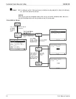
1. Operation Flowchart
For detailed description of each function in the flow below, refer to the details on related function on
the following pages.
1. If the indoor unit stops or the thermostat turns OFF while in oil return operation or defrost
operation, pump down residual operation is performed on completion of the oil return operation
or defrost operation.
Stop control
(1) Stop due to error
(2) When system is in stop control
(3) Sub unit stops during master unit control
Standby control
(1) Restart standby
(2) Crankcase heater control
Startup control
(include pressure equalization before startup)
(1) Startup control in cooling
(2) Startup control in heating
Basic control
(1) Normal control
(2) Compressor PI control
(3) Operation priority and rotation of
compressors
(4) Compressor step control
(5) Electronic expansion valve PI control
(6) Step control of outdoor fans
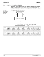
Protection control
(1) High pressure protection control
(2) Low pressure protection control
(3) Discharge pipe protection control
(4) Inverter protection control
Thermostat ON
End of
startup
control
Abnor
mality
Ther
mostat OFF
Conditions met for oil return
Special control
(1) Pump down residual operation
(4) Outdoor unit rotation
Thermostat OFF
(2) Oil return operation (note 1)
Conditions met for defrosting
(3) Defrost operation (note 1)
End of oil return operation
End of defrost operation
Conditions met for outdoor unit rotation
End of outdoor unit rotation
Содержание VRV EMERION RXYQ-AATJA
Страница 1: ...Service Manual Heat Pump 60 Hz RXYQ AATJA 208 230 V RXYQ AAYDA 460 V SiUS342303E...
Страница 380: ...Check SiUS342303E 373 Part 6 Service Diagnosis Reference Reference CHECK 7 Refer to page 379 CHECK 8 Refer to page 380...
Страница 405: ...SiUS342303E Wiring Diagrams Part 7 Appendix 398 RXYQ72 96 120 144 168 192 216 240AAYDA C 2D140769B...
Страница 406: ...Wiring Diagrams SiUS342303E 399 Part 7 Appendix 1 2 Indoor Unit FXFQ07 09 12 15 18 24 30 36 48TVJU 3D086460B...
Страница 407: ...SiUS342303E Wiring Diagrams Part 7 Appendix 400 BYCQ125BGW1 Self Cleaning Decoration Panel for FXFQ TVJU 3D076375A...
Страница 410: ...Wiring Diagrams SiUS342303E 403 Part 7 Appendix FXEQ07 09 12 15 18 24PVJU 3D098557A...
Страница 411: ...SiUS342303E Wiring Diagrams Part 7 Appendix 404 FXDQ07 09 12 18 24MVJU C 3D050501C...
Страница 413: ...SiUS342303E Wiring Diagrams Part 7 Appendix 406 FXMQ07 09 12 15 18 24 30 36 48 54PBVJU 3D093209B...
Страница 416: ...Wiring Diagrams SiUS342303E 409 Part 7 Appendix FXHQ12 24 36MVJU 3D048116C...
Страница 417: ...SiUS342303E Wiring Diagrams Part 7 Appendix 410 FXAQ07 09 12 18 24PVJU 3D075354F...
Страница 423: ...SiUS342303E Wiring Diagrams Part 7 Appendix 416 1 3 2 Energy Recovery Ventilator VAM Series VAM300 470 600GVJU 3D073269D...
Страница 424: ...Wiring Diagrams SiUS342303E 417 Part 7 Appendix VAM1200GVJU 3D073270D...