


SiUS342303E
Troubleshooting by Error Code
Part 6 Service Diagnosis
242
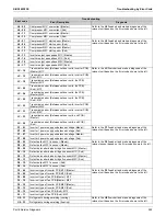
L8 - 03
Compressor M1C overcurrent (Master)
Refer to the
L8
flowchart and make a diagnosis of the
relevant unit based on the Error code shown to the left.
L8 - 06
Compressor M1C overcurrent (Sub)
L8 - 11
Compressor M2C overcurrent (Master)
L8 - 12
Compressor M2C overcurrent (Sub)
L9 - 01
Compressor M1C startup error (Master)
Refer to the
L9
flowchart and make a diagnosis of the
relevant unit based on the Error code shown to the left.
L9 - 05
Compressor M1C startup error (Sub)
L9 - 10
Compressor M2C startup error (Master)
L9 - 11
Compressor M2C startup error (Sub)
L9 - 13
Inverter output open phase M1C (Master)
L9 - 14
Inverter output open phase M1C (Sub)
L9 - 16
Inverter output open phase M2C (Master)
L9 - 17
Inverter output open phase M2C (Sub)
LC - 14
Transmission error (Between outdoor units, inverter PCB)
(Master): M1C
Refer to the
LC
flowchart and make a diagnosis of the
relevant unit based on the Error code shown to the left.
LC - 15
Transmission error (Between outdoor units, inverter PCB)
(Sub): M1C
LC - 19
Transmission error (Between outdoor units, fan PCB)
(Master): M1F
LC - 20
Transmission error (Between outdoor units, fan PCB)
(Sub): M1F
LC - 24
Transmission error (Between outdoor units, fan PCB)
(Master): M2F
LC - 25
Transmission error (Between outdoor units, fan PCB)
(Sub): M2F
LC - 30
Transmission error (Between outdoor units, inverter PCB)
(Master): M2C
LC - 31
Transmission error (Between outdoor units, inverter PCB)
(Sub): M2C
LC - 33
Transmission error (Between outdoor units, sub PCB)
(Master)
LC - 34
Transmission error (Between outdoor units, sub PCB)
(Sub)
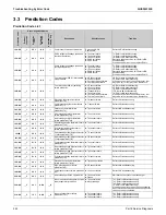
P1 - 01
Inverter 1 power supply unbalanced voltage (Master)
Refer to the
P1
flowchart and make a diagnosis of the
relevant unit based on the Error code shown to the left.
P1 - 02
Inverter 1 power supply unbalanced voltage (Sub)
P1 - 07
Inverter 2 power supply unbalanced voltage (Master)
P1 - 08
Inverter 2 power supply unbalanced voltage (Sub)
P4 - 02
Defective fan M1F fin sensor (Master)
Refer to the
P4
flowchart and make a diagnosis of the
relevant sensor based on the Error code shown to the left.
P4 - 03
Defective fan M2F fin sensor (Master)
P4 - 09
Defective inverter diode bridge fin sensor M1C (Master)
P4 - 10
Defective inverter diode bridge fin sensor M1C (Sub)
P4 - 12
Defective inverter diode bridge fin sensor M2C (Master)
P4 - 13
Defective inverter diode bridge fin sensor M2C (Sub)
P4 - 15
Defective fan M1F fin sensor (Sub)
P4 - 16
Defective fan M2F fin sensor (Sub)
PJ - 04
Incorrect type of inverter PCB M1C (Master)
Refer to the
PJ
flowchart and make a diagnosis of the
relevant unit based on the Error code shown to the left.
PJ - 05
Incorrect type of inverter PCB M1C (Sub)
PJ - 09
Incorrect type of fan PCB (Master): M1F
PJ - 10
Incorrect type of fan PCB (Master): M2F
PJ - 12
Incorrect type of inverter PCB M2C (Master)
PJ - 13
Incorrect type of inverter PCB M2C (Sub)
PJ - 15
Incorrect type of fan PCB (Sub): M1F
PJ - 17
Incorrect type of fan PCB (Sub): M2F
U0 - 31
Refrigerant shortage warning (cooling)
Refer to the
U0
flowchart and make a diagnosis of the
relevant unit based on the Error code shown to the left.
U0 - 32
Refrigerant shortage warning (heating)
Error code
Troubleshooting
Error Description
Diagnosis
Содержание VRV EMERION RXYQ-AATJA
Страница 1: ...Service Manual Heat Pump 60 Hz RXYQ AATJA 208 230 V RXYQ AAYDA 460 V SiUS342303E...
Страница 380: ...Check SiUS342303E 373 Part 6 Service Diagnosis Reference Reference CHECK 7 Refer to page 379 CHECK 8 Refer to page 380...
Страница 405: ...SiUS342303E Wiring Diagrams Part 7 Appendix 398 RXYQ72 96 120 144 168 192 216 240AAYDA C 2D140769B...
Страница 406: ...Wiring Diagrams SiUS342303E 399 Part 7 Appendix 1 2 Indoor Unit FXFQ07 09 12 15 18 24 30 36 48TVJU 3D086460B...
Страница 407: ...SiUS342303E Wiring Diagrams Part 7 Appendix 400 BYCQ125BGW1 Self Cleaning Decoration Panel for FXFQ TVJU 3D076375A...
Страница 410: ...Wiring Diagrams SiUS342303E 403 Part 7 Appendix FXEQ07 09 12 15 18 24PVJU 3D098557A...
Страница 411: ...SiUS342303E Wiring Diagrams Part 7 Appendix 404 FXDQ07 09 12 18 24MVJU C 3D050501C...
Страница 413: ...SiUS342303E Wiring Diagrams Part 7 Appendix 406 FXMQ07 09 12 15 18 24 30 36 48 54PBVJU 3D093209B...
Страница 416: ...Wiring Diagrams SiUS342303E 409 Part 7 Appendix FXHQ12 24 36MVJU 3D048116C...
Страница 417: ...SiUS342303E Wiring Diagrams Part 7 Appendix 410 FXAQ07 09 12 18 24PVJU 3D075354F...
Страница 423: ...SiUS342303E Wiring Diagrams Part 7 Appendix 416 1 3 2 Energy Recovery Ventilator VAM Series VAM300 470 600GVJU 3D073269D...
Страница 424: ...Wiring Diagrams SiUS342303E 417 Part 7 Appendix VAM1200GVJU 3D073270D...