


Troubleshooting with Remote Controller
SiUS342303E
233
Part 6 Service Diagnosis
The upper digit of the code changes as shown below.
Continuous beep :
Both upper and lower digits match. (Error code is confirmed.)
2 short beeps :
The upper digit matches but the lower digit does not.
1 short beep :
The upper digit does not match.
5. Press
MODE
button. The right
0
(lower digit) indication of the error code blinks.
6. Press
UP
button or
DOWN
button and change the error code lower digit until the receiver of the
indoor unit generates a continuous beep.
The lower digit of the code changes as shown below.
Continuous beep :
Both upper and lower digits match. (Error code is confirmed.)
2 short beeps :
The upper digit matches but the lower digit does not.
1 short beep :
The upper digit does not match.
7. Press
MODE
button to return to the normal mode. If you do not press any button for 1 minute,
the remote controller automatically returns to the normal mode.
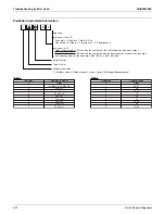
O0 A C E H F J L P U 9 8 7 6 5 4
"UP" button "DOWN" button
0 1 2 3 4 5 6 7 8 9 A H C J E F
"UP" button "DOWN" button
If no button is pressed
for 1 minute, equipment
returns to normal mode.
3. Press
MODE
button.
The upper digit
blinks.
Normal mode
1. Press
INSPECTION/TEST
button to enter
inspection mode.
7. When
MODE
button is
pressed or no button is
pressed for 1 minute,
equipment returns to
normal mode.
6. Change the lower
digit with
UP
button or
DOWN
button.
If no button is pressed
for 1 minute, equipment
returns to normal mode.
5. Press
MODE
button.
The lower digit blinks.
4. Change the
upper digit with
UP
button or
DOWN
button.
2. Change the unit number with
UP
button or
DOWN
button.
If no button is pressed
for 1 minute, equipment
returns to normal mode.
3. Pres
butto
The
blink
1. Press
INSPECTION/TEST
button to enter
inspection mode.
7. When
MODE
button is
pressed or no button is
pressed for 1 minute,
equipment returns to
normal mode.
r
If no button is pressed
for 1 minute, equipment
returns to normal mode.
5. Press
MODE
button.
The lower digit blinks.
Содержание VRV EMERION RXYQ-AATJA
Страница 1: ...Service Manual Heat Pump 60 Hz RXYQ AATJA 208 230 V RXYQ AAYDA 460 V SiUS342303E...
Страница 380: ...Check SiUS342303E 373 Part 6 Service Diagnosis Reference Reference CHECK 7 Refer to page 379 CHECK 8 Refer to page 380...
Страница 405: ...SiUS342303E Wiring Diagrams Part 7 Appendix 398 RXYQ72 96 120 144 168 192 216 240AAYDA C 2D140769B...
Страница 406: ...Wiring Diagrams SiUS342303E 399 Part 7 Appendix 1 2 Indoor Unit FXFQ07 09 12 15 18 24 30 36 48TVJU 3D086460B...
Страница 407: ...SiUS342303E Wiring Diagrams Part 7 Appendix 400 BYCQ125BGW1 Self Cleaning Decoration Panel for FXFQ TVJU 3D076375A...
Страница 410: ...Wiring Diagrams SiUS342303E 403 Part 7 Appendix FXEQ07 09 12 15 18 24PVJU 3D098557A...
Страница 411: ...SiUS342303E Wiring Diagrams Part 7 Appendix 404 FXDQ07 09 12 18 24MVJU C 3D050501C...
Страница 413: ...SiUS342303E Wiring Diagrams Part 7 Appendix 406 FXMQ07 09 12 15 18 24 30 36 48 54PBVJU 3D093209B...
Страница 416: ...Wiring Diagrams SiUS342303E 409 Part 7 Appendix FXHQ12 24 36MVJU 3D048116C...
Страница 417: ...SiUS342303E Wiring Diagrams Part 7 Appendix 410 FXAQ07 09 12 18 24PVJU 3D075354F...
Страница 423: ...SiUS342303E Wiring Diagrams Part 7 Appendix 416 1 3 2 Energy Recovery Ventilator VAM Series VAM300 470 600GVJU 3D073269D...
Страница 424: ...Wiring Diagrams SiUS342303E 417 Part 7 Appendix VAM1200GVJU 3D073270D...