SiUS342303E
Names and Functions
Part 3 Remote Controller
80
2.3 Wireless
Remote
Controller
DO
WN
FA
N
UP
O
N
OFF
M
H
L
hr.
hr.
TEST
F
MODE
TIMER
RESER
V
E CA
N
CEL
DO
WN
UP
TEST
S
W
I
N
G
FA
N
TIME
TEMP
O
N
OFF
M
H
L
hr.
hr.
TEST
F
1
3
4
6
2
5
7
8
10
9
13
11
12
15
14
16
17
1
2
3
4
5
6
7
8
hr.
hr.
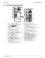
DISPLAY (SIGNAL TRANSMISSION)
DISPLAY (SET TEMPERATURE)
DISPLAY (PROGRAMMED TIME)
DISPLAY (AIRFLOW FLAP)
DISPLAY
TEST
(INSPECTION/ TEST)
DISPLAY (FAN SPEED)
ON/OFF BUTTON
Press the button and the system
w
ill start. Press
the button again and the system
w
ill stop.
This lights up
w
hen a signal is being transmitted.
This display sho
w
s the set temperature.
This display sho
w
s programmed time of the
system start or stop.
The display sho
w
s the set fan speed.
W
hen the
INSPECTION/TEST
button is pressed,
the display sho
w
s the system mode is in.
13
14
15
16
17
TIMER RESERVE/CANCEL BUTTON
AIRFLOW DIRECTION ADJUST BUTTON
OPERATION MODE SELECTOR BUTTON
FILTER SIGN RESET BUTTON
INSPECTION/TEST BUTTON
Press this button to select operation mode.
This button is used only by qualified service
persons for maintenance purposes.
11
12
Use this button for programming start and/or stop
time. (Operates
w
ith the front cover of the remote
controller opened.)
PROGRAMMING TIMER BUTTON
TIMER MODE START/STOP BUTTON
9
10
FAN SPEED CONTROL BUTTON
TEMPERATURE SETTING BUTTON
Press this button to select the fan speed, HIGH or
LO
W
, of your choice.
Use this button for setting temperature (Operates
w
ith the front cover of the remote controller
closed.)
DISPLAY
(OPERATION MODE)
This display sho
w
s the current OPERATIO
N
MODE.
M
H
L
F
Содержание VRV EMERION RXYQ-AATJA
Страница 1: ...Service Manual Heat Pump 60 Hz RXYQ AATJA 208 230 V RXYQ AAYDA 460 V SiUS342303E...
Страница 380: ...Check SiUS342303E 373 Part 6 Service Diagnosis Reference Reference CHECK 7 Refer to page 379 CHECK 8 Refer to page 380...
Страница 405: ...SiUS342303E Wiring Diagrams Part 7 Appendix 398 RXYQ72 96 120 144 168 192 216 240AAYDA C 2D140769B...
Страница 406: ...Wiring Diagrams SiUS342303E 399 Part 7 Appendix 1 2 Indoor Unit FXFQ07 09 12 15 18 24 30 36 48TVJU 3D086460B...
Страница 407: ...SiUS342303E Wiring Diagrams Part 7 Appendix 400 BYCQ125BGW1 Self Cleaning Decoration Panel for FXFQ TVJU 3D076375A...
Страница 410: ...Wiring Diagrams SiUS342303E 403 Part 7 Appendix FXEQ07 09 12 15 18 24PVJU 3D098557A...
Страница 411: ...SiUS342303E Wiring Diagrams Part 7 Appendix 404 FXDQ07 09 12 18 24MVJU C 3D050501C...
Страница 413: ...SiUS342303E Wiring Diagrams Part 7 Appendix 406 FXMQ07 09 12 15 18 24 30 36 48 54PBVJU 3D093209B...
Страница 416: ...Wiring Diagrams SiUS342303E 409 Part 7 Appendix FXHQ12 24 36MVJU 3D048116C...
Страница 417: ...SiUS342303E Wiring Diagrams Part 7 Appendix 410 FXAQ07 09 12 18 24PVJU 3D075354F...
Страница 423: ...SiUS342303E Wiring Diagrams Part 7 Appendix 416 1 3 2 Energy Recovery Ventilator VAM Series VAM300 470 600GVJU 3D073269D...
Страница 424: ...Wiring Diagrams SiUS342303E 417 Part 7 Appendix VAM1200GVJU 3D073270D...


