


SiUS342303E
97
Part 4 Functions and Control
1. Operation Flowchart..................................................................................99
2. Stop Control ............................................................................................100
5.1 Normal Control ......................................................................................... 103
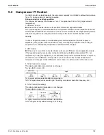
5.2 Compressor PI Control............................................................................. 104
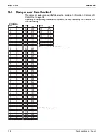
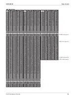
5.3 Compressor Step Control......................................................................... 105
5.4 Electronic Expansion Valve PI Control..................................................... 109
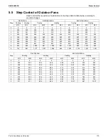
5.5 Step Control of Outdoor Fans .................................................................. 110
6.1 High Pressure Protection Control............................................................. 111
6.2 Low Pressure Protection Control.............................................................. 112
6.3 Discharge Pipe Protection Control ........................................................... 112
6.4 Inverter Protection Control ....................................................................... 113
7.1 Pump Down Residual Operation .............................................................. 115
7.2 Oil Return Operation ................................................................................ 116
7.3 Defrost Operation ..................................................................................... 118
7.4 Outdoor Unit Rotation............................................................................... 119
9.1 Operation Flowchart ................................................................................. 121
9.2 Set Temperature and Control Target Temperature.................................. 125
9.3 Remote Controller Thermistor .................................................................. 127
9.4 Thermostat Control................................................................................... 129
9.5 Drain Pump Control.................................................................................. 132
9.6 Control of Electronic Expansion Valve ..................................................... 134
9.7 Freeze-Up Prevention Control.................................................................. 135
Part 4
Functions and Control
Содержание VRV EMERION RXYQ-AATJA
Страница 1: ...Service Manual Heat Pump 60 Hz RXYQ AATJA 208 230 V RXYQ AAYDA 460 V SiUS342303E...
Страница 380: ...Check SiUS342303E 373 Part 6 Service Diagnosis Reference Reference CHECK 7 Refer to page 379 CHECK 8 Refer to page 380...
Страница 405: ...SiUS342303E Wiring Diagrams Part 7 Appendix 398 RXYQ72 96 120 144 168 192 216 240AAYDA C 2D140769B...
Страница 406: ...Wiring Diagrams SiUS342303E 399 Part 7 Appendix 1 2 Indoor Unit FXFQ07 09 12 15 18 24 30 36 48TVJU 3D086460B...
Страница 407: ...SiUS342303E Wiring Diagrams Part 7 Appendix 400 BYCQ125BGW1 Self Cleaning Decoration Panel for FXFQ TVJU 3D076375A...
Страница 410: ...Wiring Diagrams SiUS342303E 403 Part 7 Appendix FXEQ07 09 12 15 18 24PVJU 3D098557A...
Страница 411: ...SiUS342303E Wiring Diagrams Part 7 Appendix 404 FXDQ07 09 12 18 24MVJU C 3D050501C...
Страница 413: ...SiUS342303E Wiring Diagrams Part 7 Appendix 406 FXMQ07 09 12 15 18 24 30 36 48 54PBVJU 3D093209B...
Страница 416: ...Wiring Diagrams SiUS342303E 409 Part 7 Appendix FXHQ12 24 36MVJU 3D048116C...
Страница 417: ...SiUS342303E Wiring Diagrams Part 7 Appendix 410 FXAQ07 09 12 18 24PVJU 3D075354F...
Страница 423: ...SiUS342303E Wiring Diagrams Part 7 Appendix 416 1 3 2 Energy Recovery Ventilator VAM Series VAM300 470 600GVJU 3D073269D...
Страница 424: ...Wiring Diagrams SiUS342303E 417 Part 7 Appendix VAM1200GVJU 3D073270D...