


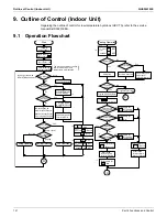


Outline of Control (Indoor Unit)
SiUS342303E
125
Part 4 Functions and Control
9.2 Set Temperature and Control Target Temperature
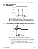
9.2.1 Without Infrared Floor Sensor
The relationship between remote controller set temperature and control target temperature is
described below.
When setting the suction air thermistor (Default setting)
When using the remote controller thermistor (Field setting is required)
Examples are given to illustrate a control target temperature that satisfies the remote controller set
temperature.
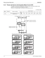
When the suction air thermistor is used for controlling (Default), the control target
temperature is determined as follows to prevent insufficient heating in heating operation.
Control target temperature = remote controller displayed tempe 2°C (3.6°F)
The temperature difference for cooling
heating mode switching is 5°C (9°F).
The above also applies to automatic operation.
Remote controller set temperature
Control target temperature
Remote controller set temperature
Control target temperature
14 15 16 17 1
8
19 20 21 22 23 24 25 26 27 2
8
29 30 31 32 33 34 35˚C
Cooling
Heating
57.2
60.
8
69.
8
62.6
71.6
64.4
73.4
66.2
75.2
59
6
8
7
8
.
8 8
0.6
8
2.4
8
4.2
77
8
7.
8 8
9.6 91.4 93.2 95˚F
8
6
Temperature
Remote controller set temperature
Control target temperature
Remote controller set temperature
Control target temperature
14 15 16 17 1
8
19 20 21 22 23 24 25 26 27 2
8
29 30 31 32 33 34 35˚C
Cooling
Heating
57.2
60.
8
69.
8
62.6
71.6
64.4
73.4
66.2
75.2
59
6
8
7
8
.
8 8
0.6
8
2.4
8
4.2
77
8
7.
8 8
9.6 91.4 93.2 95˚F
8
6
Temperature
Содержание VRV EMERION RXYQ-AATJA
Страница 1: ...Service Manual Heat Pump 60 Hz RXYQ AATJA 208 230 V RXYQ AAYDA 460 V SiUS342303E...
Страница 380: ...Check SiUS342303E 373 Part 6 Service Diagnosis Reference Reference CHECK 7 Refer to page 379 CHECK 8 Refer to page 380...
Страница 405: ...SiUS342303E Wiring Diagrams Part 7 Appendix 398 RXYQ72 96 120 144 168 192 216 240AAYDA C 2D140769B...
Страница 406: ...Wiring Diagrams SiUS342303E 399 Part 7 Appendix 1 2 Indoor Unit FXFQ07 09 12 15 18 24 30 36 48TVJU 3D086460B...
Страница 407: ...SiUS342303E Wiring Diagrams Part 7 Appendix 400 BYCQ125BGW1 Self Cleaning Decoration Panel for FXFQ TVJU 3D076375A...
Страница 410: ...Wiring Diagrams SiUS342303E 403 Part 7 Appendix FXEQ07 09 12 15 18 24PVJU 3D098557A...
Страница 411: ...SiUS342303E Wiring Diagrams Part 7 Appendix 404 FXDQ07 09 12 18 24MVJU C 3D050501C...
Страница 413: ...SiUS342303E Wiring Diagrams Part 7 Appendix 406 FXMQ07 09 12 15 18 24 30 36 48 54PBVJU 3D093209B...
Страница 416: ...Wiring Diagrams SiUS342303E 409 Part 7 Appendix FXHQ12 24 36MVJU 3D048116C...
Страница 417: ...SiUS342303E Wiring Diagrams Part 7 Appendix 410 FXAQ07 09 12 18 24PVJU 3D075354F...
Страница 423: ...SiUS342303E Wiring Diagrams Part 7 Appendix 416 1 3 2 Energy Recovery Ventilator VAM Series VAM300 470 600GVJU 3D073269D...
Страница 424: ...Wiring Diagrams SiUS342303E 417 Part 7 Appendix VAM1200GVJU 3D073270D...