


Field Setting from Outdoor Unit
SiUS342303E
207
Part 5 Field Settings and Test Operation
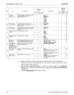
2.4.5 Heat Pump Lockout
Control logic to provide more application options for cold climates.
Outside temperature can now be measured directly from the outdoor unit coil sensor.
This field setting can switch automatically to emergency heat if there is a system fault.
Item
Description
Min
Max
Increments
Heat pump
lockout temperature
Below this temperature, heat pump is
locked out.
–15°F
(–26.1°C)
(default)
50°F
(10°C)
5°F
(2.8°C)
Heat pump lockout
release differential
When the outdoor air temperature is
recovered by this temperature, heat
pump is resumed.
5°F (2.8°C)
10°F (5.6°C) (default)
15°F (8.3°C)
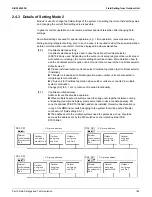
[2-16]: Auxiliary heater setting (Type I)
Value
[2-16]
Auxiliary heater
0 (default)
OFF
1
ON
[2-37]: Auxiliary heater setting (Type II)
Value
[2-37]
Controlling mode
0 (default)
OFF
1
Mode 1
2
Mode 2
3
Mode 3
4
Mode 4
5
Mode 5
6
Mode 6
Type
Description
Actions
Field
setting
Shorted
between
Heating thermostat ON
Heating thermostat OFF
Auxiliary
heater
Indoor
fan
Auxiliary
heater
Indoor
fan
I
—
Heat pump heating is
always locked out
2-16: ON
—
ON
ON (H/L)
OFF
LL
II
Mode 1
Lockout is controlled by
ABC terminals
2-37:
Mode 1
A-C
ON
ON (H/L)
OFF
LL
B-C
OFF
Mode 2
(for a heater which
does not need
airflow)
2-37:
Mode 2
A-C
LL
LL
B-C
OFF
Mode 3
Lockout is controlled by
the outdoor air
temperature and
setpoint which is
configured by the field
setting [2-47] and
[2-65]
2-37:
Mode 3
Same as 2-37: Mode 1 & A-C shorted
Mode 4
2-37:
Mode 4
Same as 2-37: Mode 1 & B-C shorted
Mode 5
2-37:
Mode 5
Same as 2-37: Mode 2 & A-C shorted
Mode 6
2-37:
Mode 6
Same as 2-37: Mode 2 & B-C shorted
Содержание VRV EMERION RXYQ-AATJA
Страница 1: ...Service Manual Heat Pump 60 Hz RXYQ AATJA 208 230 V RXYQ AAYDA 460 V SiUS342303E...
Страница 380: ...Check SiUS342303E 373 Part 6 Service Diagnosis Reference Reference CHECK 7 Refer to page 379 CHECK 8 Refer to page 380...
Страница 405: ...SiUS342303E Wiring Diagrams Part 7 Appendix 398 RXYQ72 96 120 144 168 192 216 240AAYDA C 2D140769B...
Страница 406: ...Wiring Diagrams SiUS342303E 399 Part 7 Appendix 1 2 Indoor Unit FXFQ07 09 12 15 18 24 30 36 48TVJU 3D086460B...
Страница 407: ...SiUS342303E Wiring Diagrams Part 7 Appendix 400 BYCQ125BGW1 Self Cleaning Decoration Panel for FXFQ TVJU 3D076375A...
Страница 410: ...Wiring Diagrams SiUS342303E 403 Part 7 Appendix FXEQ07 09 12 15 18 24PVJU 3D098557A...
Страница 411: ...SiUS342303E Wiring Diagrams Part 7 Appendix 404 FXDQ07 09 12 18 24MVJU C 3D050501C...
Страница 413: ...SiUS342303E Wiring Diagrams Part 7 Appendix 406 FXMQ07 09 12 15 18 24 30 36 48 54PBVJU 3D093209B...
Страница 416: ...Wiring Diagrams SiUS342303E 409 Part 7 Appendix FXHQ12 24 36MVJU 3D048116C...
Страница 417: ...SiUS342303E Wiring Diagrams Part 7 Appendix 410 FXAQ07 09 12 18 24PVJU 3D075354F...
Страница 423: ...SiUS342303E Wiring Diagrams Part 7 Appendix 416 1 3 2 Energy Recovery Ventilator VAM Series VAM300 470 600GVJU 3D073269D...
Страница 424: ...Wiring Diagrams SiUS342303E 417 Part 7 Appendix VAM1200GVJU 3D073270D...