564
Bosch Rexroth AG
| Tightening Technology
3 608 878 300
System 350
| 3 608 878 300/2019-03
IMpnio
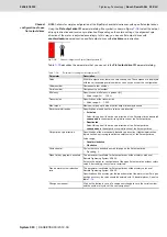
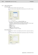
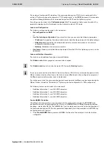
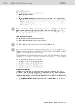
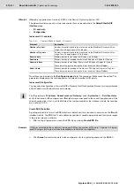
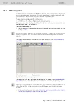
This parameter dialog contains three index cards that may be selected in the group
Set Profinet IO
interface
:
•
I/O and data
•
Configuration
•
Station information
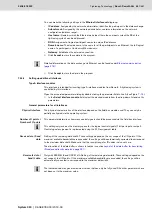
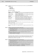
Index card: I/O and data
Input and output range mapping
In IMpnio, the cyclical process data between tightening system and communication partner is mapped
within max. 64 I/O modules.
The I/O modules are mapped within the Profinet configurator.
Case 1 The total data width is less than/equal to 64 bytes, i.e. mapping is realized exclusively in 1-byte
modules.
Case 2 If the data width it exceeds 64 bytes, it must be allocated to larger I/O modules. Starting with the
output modules, the highest module width is "filled" first, followed by the respectively next lower
applicable modules. Available are 4-word modules (quad words), 2-word modules (double words), 1-
word modules (single word) and 1-byte modules.
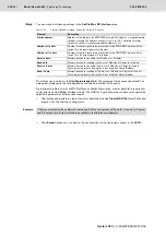
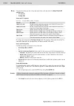
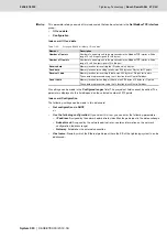
Table 7–18:
Settings in BS350 for IMpnio - I/O and data
Element
Description
Number of I points
Number of control signals to be processed via the PROFINET interface. Value range
0 to 64 input signals (0 to 8 bytes)
Number of O points
Number of control signals to be processed via the PROFINET interface. Value range
0 to 64 output signals (0 to 8 bytes)
Receive data
Memory location for receiving the ID code, max. 64 bytes
Send data
Memory location for sending results, max. 256 bytes at 0 bytes for O points
Receive IL data
Memory location for receiving IL data, max. 256 bytes at 0 bytes for I points
These data are processed using the IL function block ControlFieldbus.
Send IL data
Memory location for sending of IL data, max. 256 bytes at 0 bytes for O points
These data are processed using the IL function block ControlFieldbus.
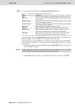
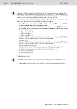
Example
Data width in tightening system of 32 bytes I and 32 bytes O:
•
A data width of 32 bytes in the input range of the tightening system correspond to the same width
in the output range of the PLC.
•
A data width of 32 bytes in the output range of the tightening system correspond to the same width
in the input range of the PLC.
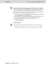
Respectively, the following applies for the number and mapping of I/O modules in the PLC
•
Setting of O modules: 32 x 1-byte module
•
Setting of I modules: 32 x 1-byte module
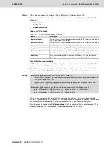
Example
Data width in tightening system of 53 bytes I and 100 bytes O:
•
A data width of 53 bytes in the input range of the tightening system correspond to the same width
in the output range of the PLC.
•
A data width of 100 bytes in the output range of the tightening system correspond to the same
width in the input range of the PLC.
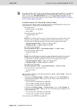
Respectively, the following applies for the number and mapping of I/O modules in the PLC
•
Setting of O modules: 6x 4-wordk 1x 2-word 1x 1-byte-module
•
Setting of I modules: 12x 4-wordk 1x 2-word module
Содержание Rexroth Tightening System 350
Страница 4: ...4 641 Bosch Rexroth AG Schraubtechnik System 350 3 608 878 300 2019 03 ...
Страница 120: ...120 641 Bosch Rexroth AG Tightening Technology 3 608 878 300 System 350 3 608 878 300 2019 03 ...
Страница 194: ...194 641 Bosch Rexroth AG Tightening Technology 3 608 878 300 System 350 3 608 878 300 2019 03 ...
Страница 638: ...638 641 Bosch Rexroth AG Tightening Technology 3 608 878 300 System 350 3 608 878 300 2019 03 ...

