3 608 878 300
Tightening Technology |
Bosch Rexroth AG 293
System 350
| 3 608 878 300/2019-03
The ID code is transferred into the tightening process once the tightening cycle has started (
CH x.y CW,
CH x.y CCW
). The tightening system evaluates the stipulated area for ID-codes (max. 64 characters in
CS351) from the data buffer. Irrelevant characters in the stipulated buffer area must be filled with spaces.
Field bus interface in the communication unit
ID-code assignment is implemented by dividing the data input field (see below).
The ID code must be stored in the data input field 100 ms before starting the tightening (
CH x.y CW,
CH x.y CCW
or
FO x CW, FO x CCW
) and remain stored until the end of tightening (
CH x.y CyCmp
,
FO
x CyCmp
) so that it can be used in the next tightening process.
The ID code is applied to the tightening process once the tightening cycle has started (start of tightening
application
FO x Cw, FO x CCW
, or start of tightening channel
Ch x.y Cw, CH x.y CCW
). The tightening
system evaluates the stipulated area for the ID-code for the respective application or tightening channel
in the data buffer (max. 64 characters). Irrelevant characters in the stipulated buffer area must be filled
with spaces.
Division of the data
input field
The division of the data input field determines which characters (bytes) from this data field will be used
for which ID code (application/single-channel tightening). This division is implemented in the BS350
operating program at
KE field bus
data
. This function is available online (with the configuration of the
connected controller) or offline (with a communication unit configuration stored on the hard drive). The
configuration of the communication unit is necessary to determine the available data fields for inputs and
outputs. To open the function, go to
System
KE field bus data
(online) or
File
New
KE field bus
data
(offline).
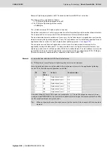
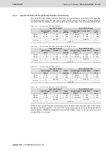
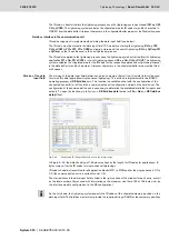
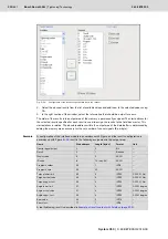
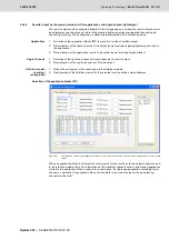
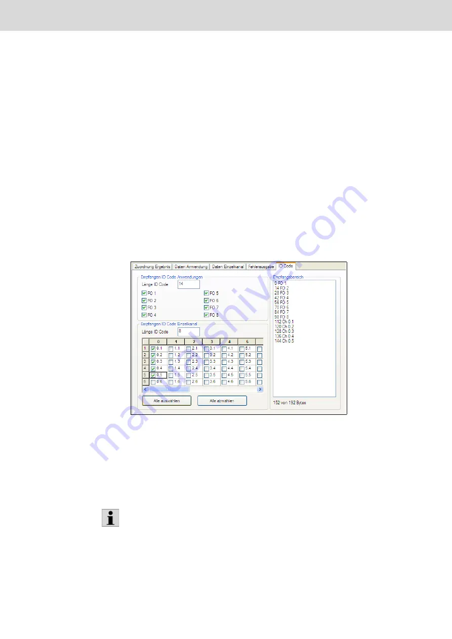
Fig. 6–49:
Determining ID code positions and sizes in the receipt range
In Figure
, the default setting of 14 bytes was kept as the length for ID codes for applications; 8
bytes were set for the ID codes for single-channel tightenings.
ID codes should be transmitted for all application blocks (FO1 to FO8) and for the single channels 0.1 to
0.5 (the communication unit is inserted into slot 0.6).
The start address in the data input field is listed in the right section of the window for each entry, as well
as the total number of bytes used with information on the maximum size (here 152 of 192 bytes) set by
the interface module configuration (in the KE configuration).
As the list shows, the tightening system expects the ID codes at the stipulated memory positions in the
data input field. The field bus master must provide the required strings (ASCII) at these memory positions.
Содержание Rexroth Tightening System 350
Страница 4: ...4 641 Bosch Rexroth AG Schraubtechnik System 350 3 608 878 300 2019 03 ...
Страница 120: ...120 641 Bosch Rexroth AG Tightening Technology 3 608 878 300 System 350 3 608 878 300 2019 03 ...
Страница 194: ...194 641 Bosch Rexroth AG Tightening Technology 3 608 878 300 System 350 3 608 878 300 2019 03 ...
Страница 638: ...638 641 Bosch Rexroth AG Tightening Technology 3 608 878 300 System 350 3 608 878 300 2019 03 ...


