3 608 878 300
Tightening Technology |
Bosch Rexroth AG 589
System 350
| 3 608 878 300/2019-03
IMpdp
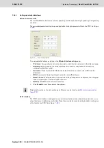
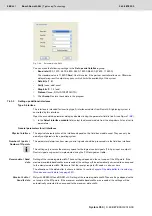
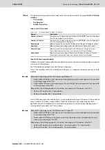
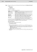
You can make the following settings in the
Set up Profibus DP interface
group:
No settings can be made in the
Configured ranges
field: The grayed out fields cannot be edited. The
parameters displayed in this field depend on the selected number of I/O points.
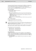
A participant profile in form of a GDS file (Generic Station Description - master data file) is required for
commissioning of the IMpdp interface module. The GSD file (
*.
gsd
) allows the software to recognize the
adjustable parameters and their value ranges.
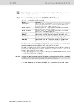
After setting all parameters, create the master data file by clicking
Create GSD file
.
Save the file and
import it into the field bus configurator.
Click
Accept
to take over this data in the configuration for the tightening channel in the BS350.
The indicated value ranges are maximum values that can only be fully used if the other parameters have
not been set to the maximum value.
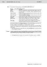
Table 7–26:
Settings in BS350 for IMpdp - I/O and data
Element
Description
Station address
Address of the IMpdp in the PROFIBUS network. The address is assigned during
field bus planning. The address section is from 2 to 123. The field bus master
(partner controller) is usually assigned the address 0 or 1.
Number of I points
Number of control signals to be processed via the PROFIBUS interface. Value
range 16 to 512 input signals (2 to 64 bytes)
Number of O points
Number of control signals to be processed via the PROFIBUS interface. Value
range 16 to 512 output signals (2 to 64 bytes)
Receive data
Memory location for receiving the ID code, max. 198 bytes at 2 bytes for I points
Send data
Memory location for sending results, max. 198 bytes at 2 bytes for O points
Receive IL data
Memory location for receiving IL data, max. 198 bytes at 2 bytes for I points
These data are processed using the IL function block ControlFieldbus.
Send IL data
Memory location for sending of IL data, max. 198 bytes at 2 bytes for O points
These data are processed using the IL function block ControlFieldbus.
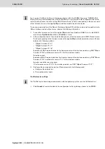
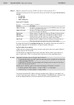
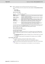
Example
If 16I was selected as the number of I points and 32O as the number of O points, 16 inputs (= 2 bytes)
and 32 outputs (= 4 bytes) will also be available in the field bus configurator.
Содержание Rexroth Tightening System 350
Страница 4: ...4 641 Bosch Rexroth AG Schraubtechnik System 350 3 608 878 300 2019 03 ...
Страница 120: ...120 641 Bosch Rexroth AG Tightening Technology 3 608 878 300 System 350 3 608 878 300 2019 03 ...
Страница 194: ...194 641 Bosch Rexroth AG Tightening Technology 3 608 878 300 System 350 3 608 878 300 2019 03 ...
Страница 638: ...638 641 Bosch Rexroth AG Tightening Technology 3 608 878 300 System 350 3 608 878 300 2019 03 ...

