300
Bosch Rexroth AG
| Tightening Technology
3 608 878 300
System 350
| 3 608 878 300/2019-03
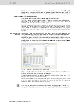
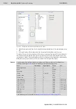
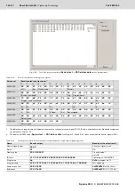
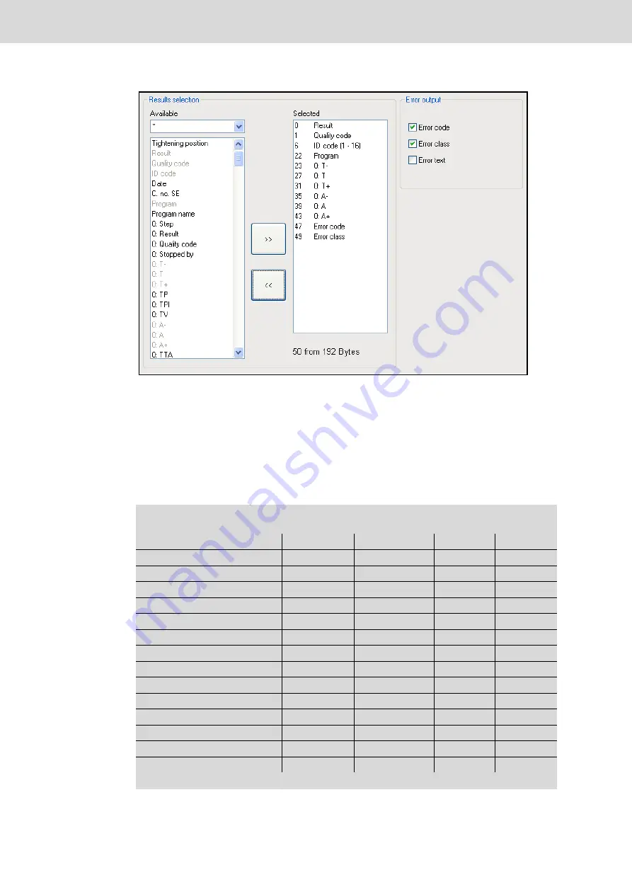
Fig. 6–52:
Configuration of the results output via field bus in the channel
2.
Select the desired results from the list of available values and add them to the selected values using
>>
.
3.
In the right section of the window, select the information that should be output for errors.
The order of the results in the output area of the memory is permanently assigned. The start address for
the selected results specified for each result is used to assign the results to the field bus master. This
start address is relative. The absolute address within the output area of the data buffer is determined by
adding the memory area necessary for the set number of control signals (8 per byte).
Example
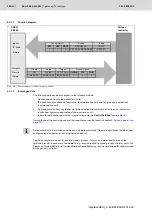
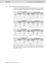
A configuration of the interface module in accordance with Figure and the results configuration in
accordance with Figure
result in the following assignment in the output area:
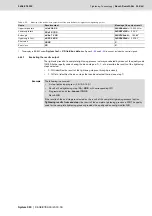
Name
Start address
Length [bytes]
Format
Unit
Control signal output
0
2
Bit
–
Result
2
1
Boolean
–
Quality code
3
5
ASCII
–
ID code
8
16 (max. 64)
ASCII
–
Program number
24
1
INT8
–
Program name
25
20
ASCII
–
Torque lower limit
45
4
INT32
0.000 01 Nm
Torque actual value
49
4
INT32
0.000 01 Nm
Torque upper limit
53
4
INT32
0.000 01 Nm
Angle lower limit
57
4
INT32
0.000 1 degree
Angle actual value
61
4
INT32
0.000 1 degree
Angle upper limit
65
4
INT32
0.000 1 degree
Error code
69
2
INT16
–
Error class
71
1
INT8
–
A real tightening result is described in
Содержание Rexroth Tightening System 350
Страница 4: ...4 641 Bosch Rexroth AG Schraubtechnik System 350 3 608 878 300 2019 03 ...
Страница 120: ...120 641 Bosch Rexroth AG Tightening Technology 3 608 878 300 System 350 3 608 878 300 2019 03 ...
Страница 194: ...194 641 Bosch Rexroth AG Tightening Technology 3 608 878 300 System 350 3 608 878 300 2019 03 ...
Страница 638: ...638 641 Bosch Rexroth AG Tightening Technology 3 608 878 300 System 350 3 608 878 300 2019 03 ...

